
Page 311 - Fiber Optic Communications Fund
P. 311
292 Fiber Optic Communications
Example 6.11
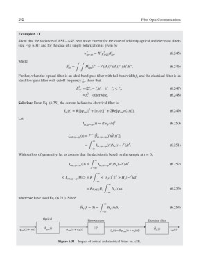
Show that the variance of ASE–ASE beat noise current for the case of arbitrary optical and electrical filters
(see Fig. 6.31) and for the case of a single polarization is given by
2 2
2
2
sp−sp = R ASE oe (6.245)
B ,
where
′
2
′′
′
′
′′
′′
B 2 oe = ∫∫ H (t − t )H (t )H (t )dt dt . (6.246)
e
e
opt
Further, when the optical filter is an ideal band-pass filter with full bandwidth f and the electrical filter is an
o
ideal low-pass filter with cutoff frequency f , show that
e
2
B =(2f − f )f if f < f , (6.247)
e e
o
o
e
oe
= f o 2 otherwise. (6.248)
Solution: From Eq. (6.25), the current before the electrical filter is
2
∗
2
I (t)= R{| | + |n (t)| + 2Re[ n (t)]}. (6.249)
in
F
out
out F
Let
2
I in,sp−sp (t)= R|n (t)| . (6.250)
F
̃
I (t)= −1 ̃ (f)H (f)]
[I
out,sp−sp in,sp−sp e
∞
′
′
′
= I in,sp−sp (t )H (t − t )dt . (6.251)
e
∫
−∞
Without loss of generality, let us assume that the decision is based on the sample at t = 0,
∞
′
′
′
I (0)= I (t )H (−t )dt . (6.252)
out,sp−sp ∫ in,sp−sp e
−∞
∞
′ 2
′
< I (0) > = R < |n (t )| > H (−t )dt ′
out,sp−sp ∫ F e
−∞
∞
B
= R ASE o ∫ H (t)dt, (6.253)
e
−∞
where we have used Eq. (6.21 ). Since
∞
̃
H (f = 0)= H (t)dt, (6.254)
e
e
∫
−∞
Optical
Photodetector Electrical filter
~ | | . 2 ~
ψ out (t) + n(t) H (f) ψ out (t) + n F (t) I in (t) = R|ψ out (t) + n F (t)| 2 H (f) I out (t)
opt
e
Figure 6.31 Impact of optical and electrical filters on ASE.