Page 307 - Fiber Optic Communications Fund
P. 307

288                                                               Fiber Optic Communications


            so that now the ASE and signal are both propagating in the forward direction. This is known as double
            Rayleigh back scattering (DRBS). The DRBS occurs not only for ASE, but also for the signal modulated by
            the data, i.e., a part of the modulated signal undergoes the DRBS process and interferes with the current bit.
            Since the Rayleigh back scattering can occur anywhere along the fiber, the part of the signal that undergoes
            DRBS has a random delay and it acts as noise on the current bit, leading to performance degradation. DRBS
            also occurs in fibers without distributed amplification. However, in the presence of Raman amplification, the
            back-scattered signal and ASE are amplified by SRS in both directions and, therefore, DRBS is one of the
            primary sources of noise in the distributed Raman amplifiers.


            6.9 Additional Examples


            Example 6.8
                                                                               ̃
                                                                     ̃
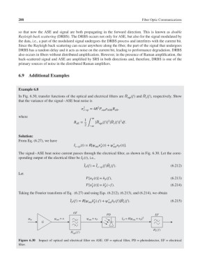
            In Fig. 6.30, transfer functions of the optical and electrical filters are H (f) and H (f), respectively. Show
                                                                                e
                                                                      opt
            that the variance of the signal–ASE beat noise is
                                               2
                                                      2
                                               s−sp  = 4R P   B ,
                                                        out ASE eff
            where                                  ∞
                                               1            2 ̃   2
                                                      ̃
                                          B  =       |H (f)| |H (f)| df.
                                           eff  2 ∫ −∞  opt    e
            Solution:
            From Eq. (6.27), we have
                                                        ∗
                                                              ∗
                                          I s−sp (t)= R[ n (t)+  n (t)].
                                                              out F
                                                     out F
            The signal–ASE beat noise current passes through the electrical filter, as shown in Fig. 6.30. Let the corre-
            sponding output of the electrical filter be I (t), i.e.,
                                              F
                                                            ̃
                                               ̃ I (f)= I ̃ s−sp (f)H (f).                   (6.212)
                                                             e
                                                F
            Let
                                                [n (t)] = ̃n (f),                           (6.213)
                                                          F
                                                   F
                                                          ∗
                                                   ∗
                                                [n (t)] = ̃n (−f).                          (6.214)
                                                   F      F
            Taking the Fourier transform of Eq. (6.27) and using Eqs. (6.212), (6.213), and (6.214), we obtain
                                                            ∗
                                                    ∗
                                                                   ̃
                                        ̃
                                        I (f)= R[ n (-f)+  n (f)]H (f).                  (6.215)
                                                              ̃
                                                   ̃
                                        F        out F      out F   e
                                         OF
                                                           PD                       EF
                  ψ in         ψ out  + n       ψ out  + n F       I O  = R∣ψ out  + n F ∣ 2
                         G
                                                                                    H e ( f )
                                        H opt ( f )
            Figure 6.30  Impact of optical and electrical filter on ASE. OF = optical filter, PD = photodetector, EF = electrical
            filter.
   302   303   304   305   306   307   308   309   310   311   312