
Page 302 - Fiber Optic Communications Fund
P. 302
Optical Amplifiers 283
The signal and pump are combined using a fiber coupler and the combined signal is launched into the fiber.
For a signal wavelength at 1550 nm, the pump wavelength should be about 1450 nm to ensure the highest gain
(corresponding to a frequency difference of about 14 THz). To achieve a gain flatness over a broad range of
signal frequencies, multiple pumps are usually used in practical systems [10].
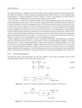
Fig. 6.23 shows a schematic of a Raman amplifier with counter-propagating pump. The advantage of a
counter-propagating pump scheme is that the transfer of power fluctuations from the pump to the signal can
be reduced compared with the co-propagating scheme. The lifetime associated with the excited state of silica
is in the range of 3 to 6 fs. Because of such a short lifetime, the transfer of power from the pump to the signal
is almost instantaneous, leading to the transfer of pump fluctuations to the signal. However, if the pump is
counter-propagating, the interaction time is equal to the transit time (= fiber length/speed of light) through
the fiber, which would be the effective lifetime. For an 80-km fiber length, the transit time is about 0.4ms,
which is much larger than the actual lifetime (in the range of femtoseconds). In the scheme of co-propagating
pumps, the pump lasers must be very quiet, i.e., they must have very low-intensity fluctuations [10]. Some
light-wave systems use both co-propagating and counter-propagating pumps.
Raman amplifiers can be divided into two types: distributed and lumped. Distributed Raman amplifiers
utilize the existing transmission fiber as a gain medium, whereas in lumped Raman amplifiers a dedicated
short-span fiber is used to provide amplification. Typically, the length of the lumped amplifier is less than
15 km. In the case of lumped amplifiers, a highly nonlinear fiber with very small effective area can be used
so that the pump intensity (= power/area) and gain can be maximized. In contrast, in the case of a distributed
Raman amplifier, the fiber parameters can not be optimized to achieve the maximum gain since the nonlinear
effects are enhanced in small-effective-area fibers which leads to performance degradation (see Chapter 10).
6.8.1 Governing Equations
Assuming the signal and pump beams are CW, the evolution of the signal and pump powers for the
forward-pumping scheme is governed by (see Section 10.11)
dP g P P
R p s
s
= − P , (6.200)
s s
dz A p
dP g P P
p p R p s
=− − P , (6.201)
p p
dz s A s
Fiber
Pump, ω p
Fiber coupler
Amplified signal
Signal, ω s
Figure 6.22 Schematic of the Raman amplifier. The pump co-propagates with the signal.
Fiber
Amplified signal
Signal Coupler
Raman pump
Figure 6.23 Schematic of the Raman amplifier in which the pump is counter-propagating.