
Page 306 - Fiber Optic Communications Fund
P. 306
Optical Amplifiers 287
Under the undepleted pump approximations, Eqs. (6.209) and (6.210) can be solved as before since the pump
is injected at z = L, the pump power at z = L, P (L) is known. Ignoring the first term on the right-hand side
p
of Eq. (6.210), the solution of Eq. (6.210) is
P (z)= P (L) exp[− (L − z)]. (6.211)
p P p
Substituting Eq. (6.211) in Eq. (6.209) and proceeding as before, we obtain the same expression for P (L) as in
s
Eq. (6.205). Thus, the gain for the forward- and backward-pumping scheme is the same under the undepleted
pump approximations.
6.8.2 Noise Figure
Spontaneous Raman scattering occurs randomly over the entire bandwidth of the amplifier and spontaneous
emission photons are amplified by SRS. The spontaneous emission factor, n , is nearly unity since a Raman
sp
system acts as a fully inverted system with the ground-state population density N ≈ 0. Therefore, the noise
1
figure of the Raman amplifier is close to 3 dB, whereas that of the EDFA is typically in the range of 4 to 8 dB.
Distributed Raman amplifiers can be imagined as tiny amplifiers placed throughout the fiber transmission line
with very small amplifier spacing. Because of the distributed nature of the amplification, the OSNR of the
distributed Raman amplifiers is higher than that of the lumped amplifiers such as EDFA (see Section 7.4.2).
6.8.3 Rayleigh Back Scattering
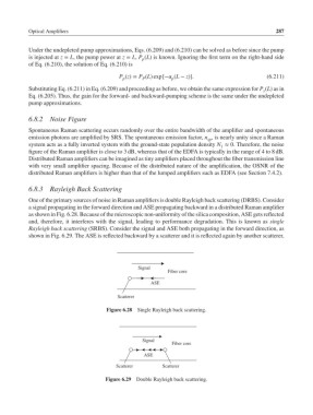
One of the primary sources of noise in Raman amplifiers is double Rayleigh back scattering (DRBS). Consider
a signal propagating in the forward direction and ASE propagating backward in a distributed Raman amplifier
as shown in Fig. 6.28. Because of the microscopic non-uniformity of the silica composition, ASE gets reflected
and, therefore, it interferes with the signal, leading to performance degradation. This is known as single
Rayleigh back scattering (SRBS). Consider the signal and ASE both propagating in the forward direction, as
shown in Fig. 6.29. The ASE is reflected backward by a scatterer and it is reflected again by another scatterer,
Signal
Fiber core
ASE
Scatterer
Figure 6.28 Single Rayleigh back scattering.
Signal
Fiber core
ASE
Scatterer Scatterer
Figure 6.29 Double Rayleigh back scattering.