Page 107 - 2006 HARLEY FLSTCI SERVICE MANUAL
P. 107

3.11


                                  2
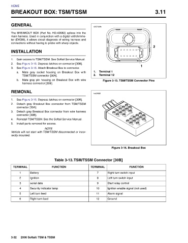
                                                       Figure 3-15. TSM/TSSM Connector Pins      Figure 3-16. Breakout Box  Right turn switch input  Left turn switch input  Start relay control Ignition enable signal (not used)


                                              1                                                              FUNCTION


                                                  Terminal 1  Terminal 12                                                    Alarm signal  Ground


                      s0474x9x                    1.  2.       hd42682                                   Table 3-13. TSM/TSSM Connector [30B]  TERMINAL  7  8  9  10  11  12


             BREAKOUT BOX: TSM/TSSM
                                                  Mate gray socket housing on Breakout Box with
                          The BREAKOUT BOX (Part No. HD-42682) splices into the
                                                       Mate gray pin housing on Breakout Box with wire
                                                                                       Vehicle will not start with TSM/TSSM disconnected or incor-
                                                                           Detach gray Breakout Box connector from wire harness
                                                                      Detach gray Breakout Box connector from TSM/TSSM
                              ter (DVOM), it allows circuit diagnosis of wiring harness and
                            main harness. Used in conjunction with a digital volt/ohmme-
                                          Gain access to TSM/TSSM. See Softail Service Manual.
                                                                   See Figure 3-15. Depress latches on connector [30B].
                                             See Figure 3-15. Depress latches on connector [30B].
                                                                               Reinstall TSM/TSSM. See the Softail Service Manual.
                                               See Figure 3-16. Attach Breakout Box to connector.
                                connections without having to probe with sharp objects.
                                                                                                             FUNCTION     Security indicator lamp
                                                                                     NOTE


                     GENERAL          INSTALLATION  TSM/TSSM connector [30A].   harness connector [30B].  REMOVAL  connector [30A].  connector [30B].  Install parts removed for access.  rectly mounted.  TERMINAL  Battery  1  Ignition  2  serial data  3  4  Left turn feed  5  Right turn feed  6  2006 Softail: TSM & TSSM


         HOME                             1.  2.  3.  a.   b.      1.  2.  3.  4.  5.                                                                   3-32
   102   103   104   105   106   107   108   109   110   111   112