
Page 1147 - 2006 HARLEY FLSTCI SERVICE MANUAL
P. 1147
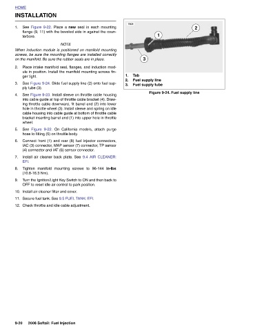
Figure 9-24. Fuel supply line
                    2


                                             Fuel supply line  Fuel supply tube
                        1

                                   3
                                           Tab
                  7908
                                           1.  2.  3.                                  in-lbs


                                                                    On California models, attach purge
                      flange (9, 11) with the beveled side in against the coun-
                    See  Figure 9-22.  Place a  new  seal in each mounting


                            NOTE When induction module is positioned on manifold mounting screws, be sure the mounting flanges are installed correctly on the manifold. Be sure the rubber seals are in place. Place intake manifold seal, flanges, and induction mod- ule in position. Install the manifold mounting screws fin- See Figure 9-24. Slide fuel supply line (2) onto fuel sup- See Figure 9-23. Install sleeve on throttle cable housing into cable guide at top of throttle cable bracket (4). Draw- ing throttle cable downward, fit barrel end (2) into lower hole in throttle wheel (3). Install sleeve and spring on idle cable housing into cable guide at bottom of throttle ca


              INSTALLATION  terbore.       ger tight.  ply tube (3).   Figure 9-22.  hose to fitting (5) on throttle body.  (10.8-16.3 Nm).  Install air cleaner filter and cover.


          HOME      1.                 2.     3.    4.           wheel.  See   5.  6.  7.  EFI.  8.  9.  10.  11.  12.                                           9-20