
Page 464 - 2006 HARLEY FLSTCI SERVICE MANUAL
P. 464
B.1 B-1
inadvertently released. Repeat the step without releas-
Secondary lock open Button Appendix B
AMP MULTILOCK ELECTRICAL CONNECTORS
NOTE If pick tool is not available, a push pin/safety pin may be An ELECTRICAL TERMINAL CRIMP TOOL (Part No. HD-41609) is used to install Amp Multi lock pin and socket terminals on wires. If new terminals must be installed, see Crimping Instructions on the next page. INSTALLING SOCKET/PIN NOTE For wire location purposes, numbers are stamped into the secondary locks of both the socket and pin housings. See From the secondary lock side of the connector, insert the terminal into its respective numbered chamber until it snaps in place. For proper fit, the slot in the terminal must face the tang in the chamber. Socket terminal
ing the tang. used instead. TERMINALS Figure B-2. Socket housing
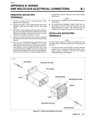
Secondary lock open Figure B-1. 10-Place Amp Multilock Connector
● ● 1. Pin housing Latch Secondary lock open
APPENDIX B–WIRING
REMOVING SOCKET/PIN Remove connector from the retaining device, either attachment or rosebud clip. Depress the button on the socket terminal side of the connector (plug) and pull apart the pin and socket Bend back the latch slightly and free one side of second- ary lock, then repeat the step to release the other side. Rotate the secondary lock outward on hinge to access terminals in chambers of connector housing. Looking in the terminal side of the connector (opposite the secondary lock), take note of the cavity next to each See Figure B-1. With the flat edge against the terminal, insert the pick tool (Snap-On TT600-3) into the cavity
HOME TERMINALS 1. 2. halves. 3. 4. terminal. 5. d0242x3x
73