
Page 468 - 2006 HARLEY FLSTCI SERVICE MANUAL
P. 468
B.2 B-5
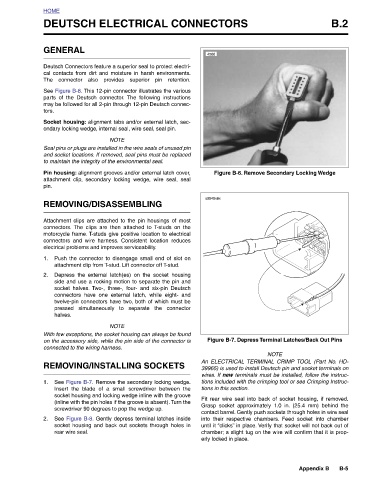
Figure B-7. Depress Terminal Latches/Back Out Pins
Figure B-6. Remove Secondary Locking Wedge
Appendix B
NOTE An ELECTRICAL TERMINAL CRIMP TOOL (Part No. HD- 39965) is used to install Deutsch pin and socket terminals on wires. If new terminals must be installed, follow the instruc- tions included with the crimping tool or see Crimping Instruc- Fit rear wire seal into back of socket housing, if removed. Grasp socket approximately 1.0 in. (25.4 mm) behind the contact barrel. Gently push sockets through holes in wire seal into their respective chambers. Feed socket into chamber until it “clicks” in place. Verify that socket will not back out of c
tions in this section. erly locked in place.
DEUTSCH ELECTRICAL CONNECTORS
4566 s0545x8x
may be followed for all 2-pin through 12-pin Deutsch connec-
Socket housing: alignment tabs and/or external latch, sec-
parts of the Deutsch connector. The following instructions
cal contacts from dirt and moisture in harsh environments.
Deutsch Connectors feature a superior seal to protect electri-
The connector also provides superior pin retention.
See Figure B-8. This 12-pin connector illustrates the various
ondary locking wedge, internal seal, wire seal, seal pin.
NOTE Seal pins or plugs are installed in the wire seals of unused pin and socket locations. If removed, seal pins must be replaced to maintain the integrity of the environmental seal. Pin housing: alignment grooves and/or external latch cover, attachment clip, secondary locking wedge, wire seal, seal REMOVING/DISASSEMBLING Attachment clips are attached to the pin housings of most connectors. The clips are then attached to T-studs on the motorcycle frame. T-studs give positive location to electrical connectors and wire harness. Consistent location reduces electrical problems and improves serviceability. Push t
GENERAL halves. connected to the wiring harness. rear wire seal.
HOME tors. pin. 1. 2. 1. 2.