Page 473 - 2006 HARLEY FLSTCI SERVICE MANUAL
P. 473

B.3                                                                              HEMET RYAN AIRPORT, P .O. BOX 878  JDG360-1
                                                                                                   HEMET, CA.  92343-0161  (714) 929-120
                                                                                                     INDUSTRIAL PRODUCTS DIV
                                                                                                         HDT - 48 - 00


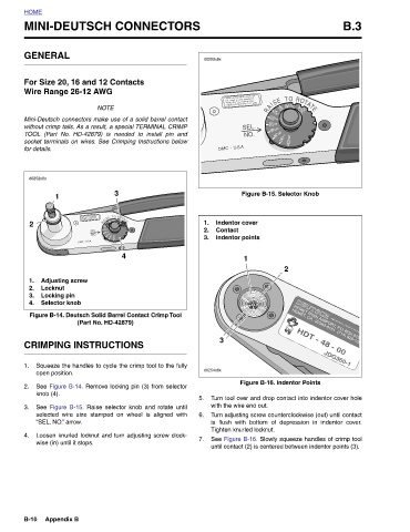
                                                                Figure B-15. Selector Knob  2                            Figure B-16. Indentor Points Turn tool over and drop contact into indentor cover hole Turn adjusting screw counterclockwise (out) until contact is flush with bottom of depression in indentor cover. See Figure B-16. Slowly squeeze handles of crimp tool until contact (2) is centered between indentor points (3).


                                   This HAND tool must not  be used in any powered  "PRESS'' as defined by OSHA CFR 1910.211 (46)  Indentor cover  Contact  Indentor points  1  with the wire end out.   Tighten knurled locknut.


                        d0253x8x                                                                            3        d0254x8x
                                                                           2.
                                                                         1.
                                                                             3.
                                                                                                                             5.   6.     7.
               MINI-DEUTSCH CONNECTORS
                                                 socket terminals on wires. See Crimping Instructions below
                                            without crimp tails. As a result, a special TERMINAL CRIMP
                                          Mini-Deutsch connectors make use of a solid barrel contact
                                               TOOL (Part No. HD-42879) is needed to install pin and

                               For Size 20, 16 and 12 Contacts


                                                                                   4
                                                                3      This HAND tool must not  be used in any powered  "PRESS'' as defined by OSHA CFR 1910.211 (46)  Figure B-14. Deutsch Solid Barrel Contact Crimp Tool   (Part No. HD-42879)  CRIMPING INSTRUCTIONS Squeeze the handles to cycle the crimp tool to the fully See Figure B-14. Remove locking pin (3) from selector See  Figure B-15.  Raise selector knob and rotate until selected wire size stamped on wheel is aligned with Loosen knurled locknut and turn adjusting screw clock-
                                       NOTE


                       GENERAL    Wire Range 26-12 AWG           1                        Adjusting screw  Locknut  Locking pin  Selector knob  open position.  knob (4).   “SEL. NO.” arrow.   wise (in) until it stops.  Appendix B


                                                   for details.  d0252x8x
             HOME                                                        2                1.  2.  3.  4.           1.     2.    3.      4.                       B-10
   468   469   470   471   472   473   474   475   476   477   478