
Page 475 - 2006 HARLEY FLSTCI SERVICE MANUAL
P. 475
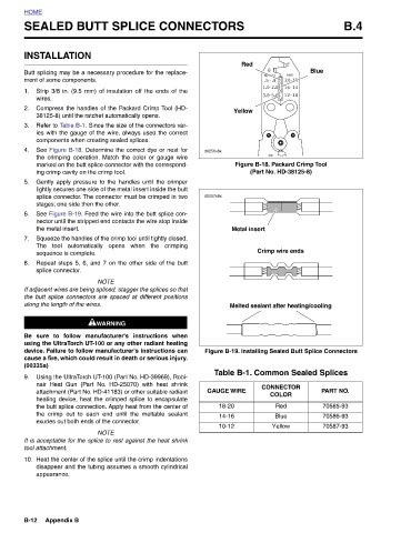
B.4                                                                                                        PART NO.  70585-93  70586-93  70587-93


                                                       Figure B-18. Packard Crimp Tool  (Part No. HD-38125-8)  Crimp wire ends  Melted sealant after heating/cooling  Figure B-19. Installing Sealed Butt Splice Connectors  Table B-1. Common Sealed Splices  CONNECTOR   COLOR  Red  Blue  Yellow
                            Blue


                          Red           Yellow                             Metal insert


                                                   d0256x8x      d0257x8x                                                  GAUGE WIRE  18-20  14-16  10-12


               SEALED BUTT SPLICE CONNECTORS  Butt splicing may be a necessary procedure for the replace- Strip 3/8 in. (9.5 mm) of insulation off the ends of the Compress the handles of the Packard Crimp Tool (HD- Refer to Table B-1. Since the size of the connectors var- ies with the gauge of the wire, always used the correct See Figure B-18. Determine the correct dye or nest for the crimping operation. Match the color or gauge wire marked on the butt splice connector with the correspond- Gently apply pressure to the handles until the crimper lightly secures one side of the metal insert inside the butt splice connector. The connector must be crimped in two See Fi


                       INSTALLATION  ment of some components.              the metal insert.  sequence is complete.  splice connector.  along the length of the wires.  tool attachment.  appearance.  Appendix B
                                         38125-8) until the ratchet automatically opens.  components when creating sealed splices.  ing crimp cavity on the crimp tool.   stages; one side then the other.  exudes out both ends of the connector.


          HOME                    1.  wires.  2.  3.  4.     5.       6.     7.      8.                            (00335a)  9.                10.               B-12