
Page 29 - report P Lemoine feb 2013c
P. 29
29
ANNEX B
Nanoindentation; principles of operation and data analysis method.
The Nanoindenter is a depth sensing indenter. It characterises the mechanical
properties of thin films or bulk samples and, since the instrument has nanometer and
nanoNewton resolution, it can measure "nano-mechanical" properties. A schematic
description is shown in figure B1, a photograph is shown in figure B2.
Coil
Current source
Oscillation
Capacitive
Displ. sensor
Lock-in amplifier
Leaf Springs
Displacement
sensor
Column
Tip
Lat. Force Sample
sensor
XY stage Computer
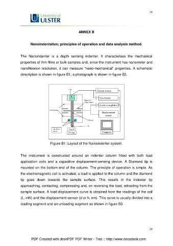
Figure B1: Layout of the Nanoindenter system.
The instrument is constructed around an indenter column fitted with both load
application coils and a capacitive displacement-sensing device. A Diamond tip is
mounted on the bottom end of the column. The principle of operation is simple. As
the electromagnetic coil is activated, a load is applied to the column and the diamond
tip goes down towards the sample surface. This results in the indenter tip
approaching, contacting, compressing and, on reversing the load, retracting from the
sample surface. A load-displacement curve is obtained from the readings of the coil
(L, mN) and the displacement sensor (d or h, nm). This curve is usually divided into a
loading segment and an unloading segment as shown in figure B3.
29
PDF Created with deskPDF PDF Writer - Trial :: http://www.docudesk.com