
Page 241 - TORO PRODUCT CATALOGUE NOV_2019
P. 241
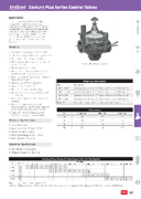
    R Century Plus Series Control Valves
        Application
These heavy-duty globe/angle valves, designed primarily for commercial applications, offer superior performance and durability under the most demanding conditions. Tracing its origin back to the highly popular Century Series, the 100 Series (Century PLUS) delivers reliable performance with a host of enhanced features.
Features
• Available in 25, 40, 50 and 80 mm BSP
• 1500 kPa rating (820 kPa if using DCLS-P)
• Manual internal and external bleed
• Flow control allows flow adjustment and manual shutoff
• Globe/angle configuration
• Glass-reinforced nylon body withstands high temperatures under pressure
• Rugged, double-beaded, nylon-reinforced Buna-N diaphragm
• Stainless steel metering system
• Captive plunger solenoid
• Positive O-ring seal on inlet plug
• Moulded-in studs allow positive bonnet attachment
• Brass flow control stem (50 and 80 mm models)
• Pressure Regulation (OmniReg® modular option). See OmniReg® page for performance data and specifications.
• 9–12 VDC Latching Solenoid option (DCLS-P) (max. pressure 820 kPa)
Electrical Specifications
• Solenoid: 24 VAC
• Inrush volt-amp: 24 VAC - 9.6 VA • Inrush current: 0.4 amp
• Holding volt-amp: 24 VAC - 4.8 VA • Holding current: 0.2 amp
Operating Specifications
• Flow range: 20-1100 Lpm
• Pressure range: 70-1500 kPa
Flow rates are recommended not to exceed 35 kPa loss.
Century Plus Commercial Valve
        Ordering Information
 Code
   Description
   100P1-BSP
 Century Plus 25 mm FBSP Solenoid Valve with Flow Control
 100P1.5-BSP
  Century Plus 40 mm FBSP Solenoid Valve with Flow Control
 100P2-BSP
  Century Plus 50 mm FBSP Solenoid Valve with Flow Control
 100P3-BSP
  Century Plus 80 mm FBSP Solenoid Valve with Flow Control
 HVC-KIT
  Hydraulic Conversion Kit for Century Series Valves
    Dimensions
 Size
   Height (mm)
  Width (mm)
  Depth (mm)
  25
 172
92
  121
 40
  185
 92
 121
 50
  242
 156
 197
 80
   273
 156
 210
         Century Plus Series Friction Loss (kPa) vs Flow (Lpm)
 Size
 Configuration
      Flow Rate Lpm
  20
  40
  60
  80
  100
  120
  140
  160
  180
  200
  250
  300
  350
  400
  450
  500
  550
  600
  700
  800
  900
  1000
  1100
  25 mm
 Globe Angle
  43 43
29 29
  25 25
23 21
  26 20
32 21
  43 29
 55 38
69 49
                40 mm
 Globe Angle
      12 9
 14 10
 18 13
 23 17
 28 22
 43 34
 62 48
 85 65
 111 85
          50 mm
 Globe Angle
             20 12
 25 15
 32 19
 40 24
 48 29
 54 32
      80 mm
 Globe Angle
                           18 14
 24 19
  32 26
 41 34
  52 43
 65 54
  Note: when designing a system, the industry standard maximum flow rate velocity through pipes and fittings is 2m/s. Please refer to relevant pipe velocity data.
 225
