
Page 123 - SAPEM-Chapter-10-2nd-edition-2014
P. 123
South African Pavement Engineering Manual
Chapter 10: Pavement Design
8. STRUCTURAL CAPACITY ESTIMATION: CONCRETE PAVEMENTS
The first formal design method for concrete pavements in South Africa was included in Manual M10: Concrete
Pavement Design and Construction (1995). It became apparent from overseas research, performance of local
pavements and some instrumented sections of a concrete inlay on the N3 that the method was inherently
conservative, and thus resulted in expensive pavements. A new design method to design cost effective pavements
was needed. It also needed to be mechanistically based, to facilitate interaction with the mechanistic flexible
pavement design methods. The mechanistic-empirical design method for concrete pavements was developed, based
on the same principles as in the Manual M10. This method is implemented in the software package cncPAVE. Both
these methods are based on the principle that the joint or a transverse crack is the weakest point in the pavement
and load transfer, as defined in terms of relative vertical movement under a passing wheel load or under the FWD, is
therefore the basis for predicting structural performance.
Brief overviews of the following methods for concrete pavements are discussed in this section:
• Manual M10
• Mechanistic-empirical design method (cncPAVE)
8.1 Manual M10
Manual M10 was developed from the AASHTO method for concrete pavements (M10, 1995). The AASHTO method
essentially follows a recipe type approach to design and uses a series of nomograms, but it does contain some
aspects of mechanistic design (AASHTO, 1993). For Manual M10, the AASHTO method was refined, validated and
simplified for South African conditions. It is discussed here in some detail, as it provides a good idea of the basic
elements of structural capacity estimation for concrete pavements.
Manual M10 essentially follows this sequence for designing concrete pavements:
• Determine axle group loading
• Select stiffness moduli used for slab support layers
• Use nomograph to get equivalent support stiffness
• Use nomograph to determine relative vertical movement at joint/crack, i.e., load transfer
• Use nomograph to obtain slab thickness
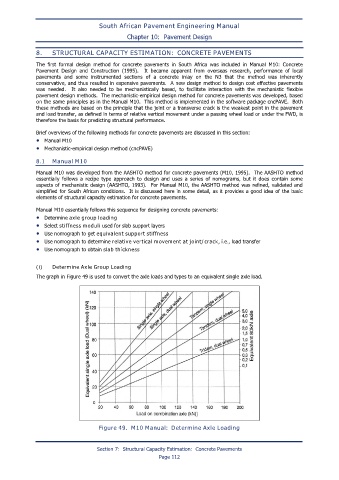
(i) Determine Axle Group Loading
The graph in Figure 49 is used to convert the axle loads and types to an equivalent single axle load.
Figure 49. M10 Manual: Determine Axle Loading
Section 7: Structural Capacity Estimation: Concrete Pavements
Page 112