
Page 88 - SAPEM-Chapter-10-2nd-edition-2014
P. 88
South African Pavement Engineering Manual
Chapter 10: Pavement Design
The stiffness in a granular layer depends on the strength of the support; the stronger the underlying layer, the stiffer
the granular layer. For rehabilitation investigations, it is important to realise that wide ranges can exist for the same
material, depending on the in situ state.
Table 29. Elastic Moduli for Granular Materials
Material Material Description Elastic Modulus
Code Support Condition
Over Cemented Over Granular
1
G1 High quality crushed stone 250 – 1000 (450) 150 – 600 (300)
G2 Crushed stone 200 – 800 (400) 100 – 400 (250)
G3 Crushed stone 200 – 800 (350) 100 – 350 (250)
G4 Natural gravel (base quality) 100 – 600 (300) 75 – 350 (225)
G5 Natural gravel 50 – 400 (250) 40 – 300 (200)
G6 Natural gravel (subbase quality) 50 – 200 (225) 30 – 200 (150)
EG4 Equivalent granular, G5/G6 parent material – 200 – 400 (300)
EG5 Equivalent granular, G7/G8 parent material – 100 – 300 (200)
EG6 Equivalent granular, G9/G10 parent material – 30 – 200 (140)
Note
1. Values shown in brackets were used for the development of the catalogues in TRH4 (1996).
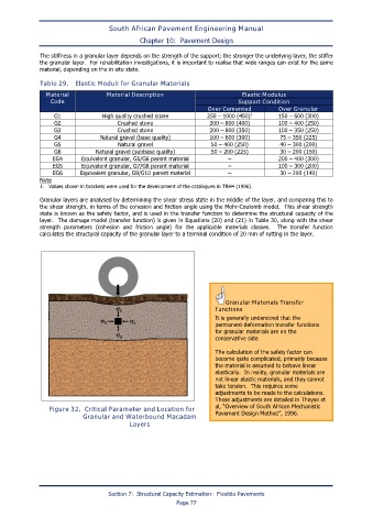
Granular layers are analysed by determining the shear stress state in the middle of the layer, and comparing this to
the shear strength, in terms of the cohesion and friction angle using the Mohr-Coulomb model. This shear strength
state is known as the safety factor, and is used in the transfer function to determine the structural capacity of the
layer. The damage model (transfer function) is given in Equations (20) and (21) in Table 30, along with the shear
strength parameters (cohesion and friction angle) for the applicable materials classes. The transfer function
calculates the structural capacity of the granular layer to a terminal condition of 20 mm of rutting in the layer.
Granular Materials Transfer
σ 1 Functions
σ 3 σ 3 It is generally understood that the
permanent deformation transfer functions
σ 3 for granular materials are on the
conservative side.
The calculation of the safety factor can
become quite complicated, primarily because
the material is assumed to behave linear
elastically. In reality, granular materials are
not linear elastic materials, and they cannot
take tension. This requires some
adjustments to be made to the calculations.
These adjustments are detailed in Theyse et
Figure 32. Critical Parameter and Location for al, “Overview of South African Mechanistic
Pavement Design Method”, 1996.
Granular and Waterbound Macadam
Layers
Section 7: Structural Capacity Estimation: Flexible Pavements
Page 77