
Page 93 - SAPEM-Chapter-10-2nd-edition-2014
P. 93
South African Pavement Engineering Manual
Chapter 10: Pavement Design
Table 33. Transfer Function and Constants for Shear Failure (Waterbound Macadam)
log N = α + 0.075 RD − 0.009 S + 0.028 PS − 1.643 SR (22)
= Number of equivalent standard axles to safeguard against shear failure
Where N
α = Constant for Reliability Level, given below
RD = Relative Density
S = Saturation
PS = Plastic strain, calculated as the terminal rut depth (% of layer thickness)
SR = Stress Ratio, defined in Equation (23)
�σ − σ �
SR = φ 1 3 φ (23)
2
σ ��tan �45 + � − 1�� + 2 C tan �45 + �
3
2 2
a
Where σ 1 = Applied major principal stress (kPa)
σ 3 = Minor principle stress acting in the middle of the granular layer
1
(compressive stress positive)
C = Cohesion
φ = Angle of Internal Friction, calculated using Equation (24)
C = Cohesion, recommended value = 74 kPa
φ = −26.38 + 1.021 RD − 0.171 S (24)
Constants for Equation (22)
Reliability Level α
95% (Category A) 1.601
90% (Category B) 1.661
80% (Category C) 1.731
50% (Category D) 1.861
Notes
1. If a tensile stress, i.e., a negative σ 3 is calculated, σ 3 is reset to zero and σ 1 is increased by the value of σ 3. The net result is
that (σ 1 – σ 3) remains the same, and σ 3 = 0.
7.1.4 Cement Stabilized Base and Subbase Layers
(i) 1996 SAMDM
Cement stabilized layers are analysed as bound layers
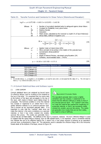
for effective fatigue, and for crushing of the material at Equivalent Granular State
the top of the layer. It is assumed that the cracks start The equivalent granular state is when a lightly
at the bottom of the layer and propagate to the top of cemented layer has cracked or weakened to the
the layer, with cracks in thicker layers taking longer to extent that the effective stiffness is similar to that of
propagate. The terminal condition is when the material an unbound granular layer. The “cracked” state does
has cracked or weakened to an extent that it has a not imply the material has reached the consistency of
similar effective stiffness to an unbound granular layer. a granular material, or that it has necessarily visibly
This is known as the equivalent granular state. It is cracked into smaller, granular like pieces. The cracks
important to note that the “cracked” state does not are generally micro-cracks that are not that visible,
imply the material is the same consistency as a granular but result in a loss of stiffness.
material, or that it has visibly cracked into smaller,
granular like pieces. The cracks are generally micro-
cracks that are not that visible. The stiffness of the layer is, however, reduced. The term “effective fatigue” is used
to suggest that the typical fatigue cracking, such as with asphalt layers, is not expected. Once a cemented material
has reached the end of its effective fatigue life, is enters into a new phase wherein it behaves as an equivalent
granular layer, as illustrated in Figure 34. The parameter used to calculate the effective fatigue life is the horizontal
tensile strain at the bottom of the layer, shown in Figure 35.
Section 7: Structural Capacity Estimation: Flexible Pavements
Page 82