
Page 52 - Basics of Electrical, Electronic and Communication
P. 52
14.5. Data acquisition systems 289
Sensor 1 Signal
Conditioner 1
Sensor 2 Signal
Conditioner 2 Multiplexer Buffer Sample
..... ..... amplifier and hold
Sensor N Signal
Conditioner N
ADC Computer
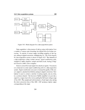
Figure 14.5: Block diagram for a data acquisition system
Data acquisition is the process of taking analog information from
a number of sources and converting into digital form for further pro-
cessing. It consists of several stages including sampling of the sig-
nal, analog to digital conversion, multiplexing, etc. The block diagram
for data acquisition system is shown in Figure 14.5. The elements of
a data acquisition system include sensors, signal conditioning units,
multiplexer, buffer amplifier, sample and hold circuit, Analog to Digi-
tal Converter (ADC) and a computer.
Sensors convert the input signal into electrical signals. The sensors
are connected via some signal conditioning units to a data acquisition
system. Signal conditioners are used to increase the quality of the sen-
sor output to a desired level before analog-to-digital conversion. Mul-
tiplexer is used to connect a number of analog signals, one at a time,
to a common channel. The function of buffer amplifier is to provide a
signal in a range close to but not exceeding the full input voltage range
of the ADC. The sample and hold maintains a fixed input value during
the short conversion time of the ADC. ADC produces digital output
corresponding to the input.
289