
Page 340 - Womens Pavilion
P. 340
Oil-Less Claw Medical Vacuum
Appendix B: Variable Speed Drive Inverter
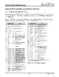
B.3.4 Trouble Shooting (Alarm Indications)
When an alarm occurrs in the inverter, the protective function is activated bringing the inverter to an
alarm stop and the monitor display automatically changes to any of the following alarm indications
(see Table B.3.4).
When the protective function is activated, take the corresponding corrective action (refer to factory),
then reset the inverter and resume operation. (See Reset VSD Section B.3.3)
Operation Panel Name Operation Panel Refer
Indication Indication Name to
E--- Alarm history E.GF Output side ground fault 251
overcurrent
HOLD Operation panel lock E.LF Output phase failure 251
Error message to Er1 to 4 Parameter write error E.OHT External thermal relay 251
operation *2
251
E.PTC* PTC thermistor operation
to
rE1 to 4 Copy operation error
252
E.OPT Option alarm
E.OP1 Communication option alarm 252
Err. Error
OL Stall prevention (overcurrent) E. 1 Option alarm 252
Parameter storage device
oL Stall prevention (overvoltage) E.PE 252
alarm
RB Regenerative brake prealarm E.PUE PU disconnection 252
Warnings TH Electronic thermal relay E.RET Retry count excess 253
function prealarm
Parameter storage device
PU stop
PS
MT Maintenance signal output Major fault / E.PE2* alarm 252
E. 6 /
CP Parameter copy / E.CPU 253
E. 7 / CPU error
Minor fault FN Fan fault Operation panel power
supply short circuit, RS-485
Overcurrent shut-off during E.CTE terminal power supply short 253
circuit
E.OC1
acceleration 24VDC power output short
E.P24 253
Overcurrent shut-off during
E.OC2 circuit
constant speed Output current detection
Overcurrent shut-off during E.CDO* value exceeded 253
E.OC3
deceleration or stop Inrush current limit circuit
Regenerative overvoltage E.IOH* alarm 253
E.OV1
shut-off during acceleration Communication error
E.SER* 254
Regenerative overvoltage
E.OV2 (inverter)
shut-off during constant speed E.AIE* Analog input error 254
Regenerative overvoltage shut- E.13 Internal circuit error 254
E.OV3
Major fault E.THT Inverter overload shut-off * If an error occurs when using the FR-PU04/FR-PU07, "Fault 14" is
off during deceleration or stop
(electronic thermal relay function)
displayed on the FR-PU04/FR-PU07.
Motor overload shut-off
E.THM
(electronic thermal relay function)
Table B.3.4 List of Alarm Displays
E.FIN Fin overheat
E.IPF Instantaneous power failure
Brake transistor alarm
E.BE
detection/internal circuit error
E.UVT Undervoltage
E.ILF* Input phase failure
E.OLT Stall prevention
B-21 4107 9000 95.04