
Page 147 - ansys
P. 147
9.4 Displaying Pathlines
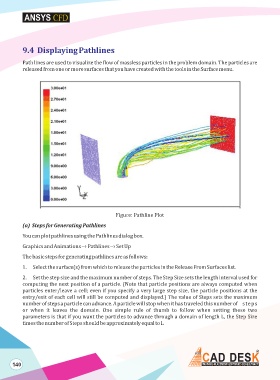
Path lines are used to visualize the flow of massless particles in the problem domain. The particles are
released from one or more surfaces that you have created with the tools in the Surface menu.
Figure: Pathline Plot
(a) Steps for Generating Pathlines
You can plot pathlines using the Pathlines dialog box.
Graphics and Animations –› Pathlines –› Set Up
The basic steps for generating pathlines are as follows:
1. Select the surface(s) from which to release the particles in the Release From Surfaces list.
2. Set the step size and the maximum number of steps. The Step Size sets the length interval used for
computing the next position of a particle. (Note that particle positions are always computed when
particles enter/leave a cell; even if you specify a very large step size, the particle positions at the
entry/exit of each cell will still be computed and displayed.) The value of Steps sets the maximum
number of steps a particle can advance. A particle will stop when it has traveled this number of steps
or when it leaves the domain. One simple rule of thumb to follow when setting these two
parameters is that if you want the particles to advance through a domain of length L, the Step Size
times the number of Steps should be approximately equal to L
140