
Page 33 - ansys
P. 33
Variable Radius Blend: The Fixed-Radius feature allows you to create blends on model edges. This
feature can be executed on both frozen and active bodies beginning in version 11.0. Prior to version
11.0, this feature would only operate on active bodies. You can preselect 3D edges and/or faces for
blending, and select 3D edges and/or faces while in the blend creation itself. If you select a face, all the
edges from that face are blended. Preselection allows additional options from a right mouse button
context menu for face edge loop selection and smooth 3D edge chain selection from the model. You can
edit the blend radius in the Details View. Clicking Generate completes the feature creation and updates
the model.
Vertex Blend: The Vertex Blend feature allows you to create blends at vertices on Solid, Surface or line
bodies. This feature can be executed on both frozen and active bodies. You can pre-select model
vertices or use the Apply/Cancel property to make your selections. In order to blend a vertex, it must
satisfy the following conditions:
w The vertex must connect to exactly two edges.
w The geometry surrounding the vertex must be planar. This means the two adjacent edges must be
co-planar and the adjacent face, if there is one, must also be planar.
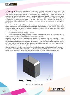
Chamfer: You can preselect 3D edges and/or faces for chamfering, and/or you can select 3D edges
and/or faces while in the chamfer creation itself. If a face is selected, all the edges from that face are
chamfered. Preselection allows additional options from a right mouse button context menu for face
edge loop selection and smooth 3D edge chain selection from the model. Every edge on a face has a
direction. This direction defines a right and left side.
Chamfer is defined either by two distances from the edge for the planar transition (chamfer face), or by
a distance (left or right) and an angle. The type of chamfer is defined in the Details View along with the
distances and angle. Clicking Generate completes the feature creation and updates the model.
Figure 2.12: Chamfered Edge
26