
Page 316 - Теория кавитации
P. 316
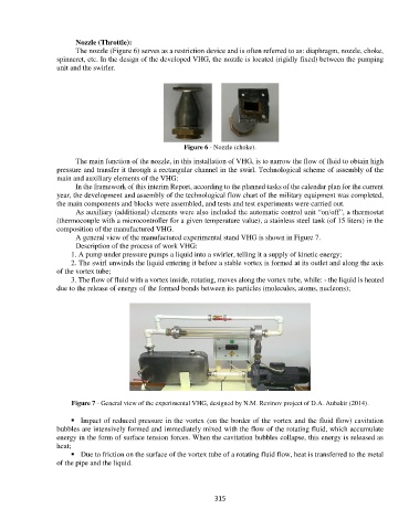
Nozzle (Throttle):
The nozzle (Figure 6) serves as a restriction device and is often referred to as: diaphragm, nozzle, choke,
spinneret, etc. In the design of the developed VHG, the nozzle is located (rigidly fixed) between the pumping
unit and the swirler.
Figure 6 - Nozzle (choke).
The main function of the nozzle, in this installation of VHG, is to narrow the flow of fluid to obtain high
pressure and transfer it through a rectangular channel in the swirl. Technological scheme of assembly of the
main and auxiliary elements of the VHG:
In the framework of this interim Report, according to the planned tasks of the calendar plan for the current
year, the development and assembly of the technological flow chart of the military equipment was completed,
the main components and blocks were assembled, and tests and test experiments were carried out.
As auxiliary (additional) elements were also included the automatic control unit “on/off”, a thermostat
(thermocouple with a microcontroller for a given temperature value), a stainless steel tank (of 15 liters) in the
composition of the manufactured VHG.
A general view of the manufactured experimental stand VHG is shown in Figure 7.
Description of the process of work VHG:
1. A pump under pressure pumps a liquid into a swirler, telling it a supply of kinetic energy;
2. The swirl unwinds the liquid entering it before a stable vortex is formed at its outlet and along the axis
of the vortex tube;
3. The flow of fluid with a vortex inside, rotating, moves along the vortex tube, while: - the liquid is heated
due to the release of energy of the formed bonds between its particles (molecules, atoms, nucleons);
Figure 7 - General view of the experimental VHG, designed by N.M. Revinov project of D.A. Aubakir (2014).
Impact of reduced pressure in the vortex (on the border of the vortex and the fluid flow) cavitation
bubbles are intensively formed and immediately mixed with the flow of the rotating fluid, which accumulate
energy in the form of surface tension forces. When the cavitation bubbles collapse, this energy is released as
heat;
Due to friction on the surface of the vortex tube of a rotating fluid flow, heat is transferred to the metal
of the pipe and the liquid.
315