
Page 430 - Chief Architect Reference Manual
P. 430
Chief Architect X10 Reference Manual
Special Ceilings
By default, the program builds a flat ceiling dialog and the Ceiling Plane tool.
platform on top the wall plates of a room. Ceiling planes are drawn and can be edited
More varied and complex ceilings are made much like roof planes. See “Ceiling Planes”
using settings in the Room Specification on page 811.
Lowered Ceilings
You can define a lowered or dropped ceiling 3. On the STRUCTURE panel, click the Ceil-
in a room without affecting the top height of ing Finish button to open the Ceiling
the walls by specifying the lowered ceiling Finish Definition dialog. See “Material
framing as a layer in the ceiling finish. Layers Definition Dialogs” on page
1001.
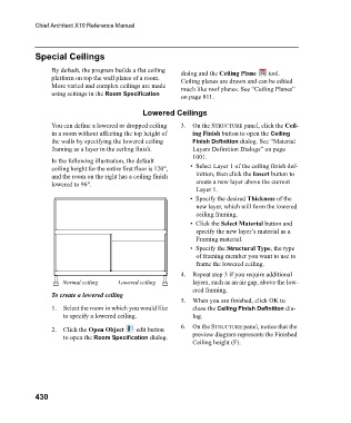
In the following illustration, the default
ceiling height for the entire first floor is 120", • Select Layer 1 of the ceiling finish def-
and the room on the right has a ceiling finish inition, then click the Insert button to
lowered to 96". create a new layer above the current
Layer 1.
• Specify the desired Thickness of the
new layer, which will form the lowered
ceiling framing.
• Click the Select Material button and
specify the new layer’s material as a
Framing material.
• Specify the Structural Type, the type
of framing member you want to use to
frame the lowered ceiling.
4. Repeat step 3 if you require additional
Normal ceiling Lowered ceiling layers, such as an air gap, above the low-
ered framing.
To create a lowered ceiling
5. When you are finished, click OK to
1. Select the room in which you would like close the Ceiling Finish Definition dia-
to specify a lowered ceiling. log.
2. Click the Open Object edit button 6. On the STRUCTURE panel, notice that the
to open the Room Specification dialog. preview diagram represents the Finished
Ceiling height (F).
430