
Page 811 - Chief Architect Reference Manual
P. 811
Ceiling Planes
Ceiling Planes
Ceiling planes are drawn the same • Ceiling planes should be created over
way as roof planes and are edited rooms that have Flat Ceiling Over this
using the same tools. They are useful for Room unchecked in the Room
creating custom vaulted ceilings. See Specification dialog. See “Structure
“Vaulted and Cathedral Ceilings” on page Panel” on page 436.
431. • The Baseline of a ceiling plane should be
Ceiling planes are drawn using the same drawn along the outer surface of the bear-
default pitch as roof planes, specified in the ing wall’s Main Layer. This allows the
Build Roof dialog. See “Build Roof Dialog” ceiling plane to extend over and be sup-
on page 780. ported by the wall. See “The Main Layer”
on page 383.
• The sloping edge at the side of a ceiling
plane should butt to the inside of the wall.
• Ceiling planes act independent of the roof
planes above.
• Usually, the pitch of a ceiling plane is
lower than the pitch of the corresponding
roof plane.
• Ceiling planes can be joined together
using the Join Roof Planes edit but-
ton. See “Join Roof Planes” on page 793.
• Select a ceiling plane and click the Open
Object edit button to open the Ceiling
Plane Specification dialog. See “Ceiling
Plane Specification Dialog” on page 812.
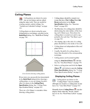
Cross Section showing ceiling planes.
Displaying Ceiling Planes
If you wish, you can specify the desired pitch
in the Build Roof dialog before drawing a Ceiling planes are drawn on the
ceiling plane, or you can change the pitch “Ceiling Planes” layer by default,
after it is drawn in the Ceiling Plane although you can place a ceiling plane on any
Specification dialog. See “Ceiling Plane layer. See “Line Style Panel” on page 815.
Specification Dialog” on page 812.
Manually drawn Ceiling Planes can also
There are a few things to remember when
drawing ceiling planes. display labels when the “Roofs, Labels”
layer is on. See “Roof Plane Labels” on page
791.
811