
Page 862 - Chief Architect Reference Manual
P. 862
Chief Architect X10 Reference Manual
platform, they bear on a wall or beam at that
point. When this is the case, place a Bearing
Wall or Bearing Beam instead of using a
Bearing Line. See “Structure Panel” on page
392 and “Floor/Ceiling Beam” on page 843.
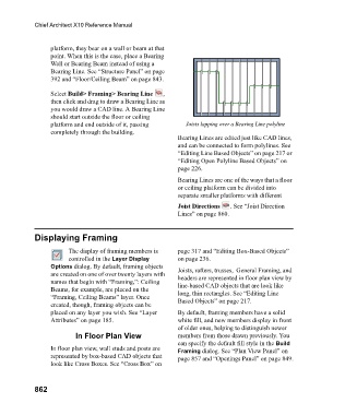
Select Build> Framing> Bearing Line ,
then click and drag to draw a Bearing Line as
you would draw a CAD line. A Bearing Line
should start outside the floor or ceiling
platform and end outside of it, passing Joists lapping over a Bearing Line polyline
completely through the building.
Bearing Lines are edited just like CAD lines,
and can be connected to form polylines. See
“Editing Line Based Objects” on page 217 or
“Editing Open Polyline Based Objects” on
page 226.
Bearing Lines are one of the ways that a floor
or ceiling platform can be divided into
separate smaller platforms with different
Joist Directions . See “Joist Direction
Lines” on page 860.
Displaying Framing
The display of framing members is page 317 and “Editing Box-Based Objects”
controlled in the Layer Display on page 236.
Options dialog. By default, framing objects Joists, rafters, trusses, General Framing, and
are created on one of over twenty layers with headers are represented in floor plan view by
names that begin with “Framing,”: Ceiling line-based CAD objects that are look like
Beams, for example, are placed on the long, thin rectangles. See “Editing Line
“Framing, Ceiling Beams” layer. Once Based Objects” on page 217.
created, though, framing objects can be
placed on any layer you wish. See “Layer By default, framing members have a solid
Attributes” on page 185. white fill, and new members display in front
of older ones, helping to distinguish newer
In Floor Plan View members from those drawn previously. You
can specify the default fill style in the Build
In floor plan view, wall studs and posts are Framing dialog. See “Plan View Panel” on
represented by box-based CAD objects that page 857 and “Openings Panel” on page 849.
look like Cross Boxes. See “Cross Box” on
862