
Page 11 - Tire Washer
P. 11
TIRE WASHER
Installation
Tunnel Placement
1) Uncrate the tire washer. DO NOT remove the steel shipping crossbeams from the assemblies.
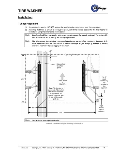
2) Assuming that there is already a conveyor in place, select the desired location for the Tire Washer to
be installed using the dimensions shown below.
Note: Brushes should face each other with arms angled toward the tunnels exit end. The driver side
Tire Washer will act as part of the conveyor guide rail.
Note: The dimensions shown below can vary depending on surrounding equipment locations. It is
most important that the tire washer is moved through its full range of motion to ensure
conveyor clearance before lagging to the floor.
1/2"
Operating Envelope
Hydraulic Motor
Cover Plate
(typical)
1” to 27”
172” actual
distance may
vary
according to
other
Note: This dimension is equipment
approximate. Adjust so that
when the Tire Washer arm
is fully retracted, the
hydraulic motor cover plate
is flush with the outside
guide rail.
Leg of
47” existing
piece of
equipment
145”
Note: Tire Washer shown fully extended.
47" dimension is taken from the outer leg to the driver side edge of the inside guide rail
1MANUL738 Belanger, Inc. * 1001 Doheny Ct. * Northville, MI 48167 * Ph (248) 349-7010 * Fax (248) 380-9681 9