
Page 15 - Full Side Washer Signature® Series
P. 15
FULL SIDE WASHER Signature ® Series
Installation
Tunnel Placement
When placing a piece of equipment, tunnel depth will vary from site to site. Be sure to allow an
adequate operating envelope
There are two traditional installation configurations for the Full Side Washer.
• Standard, stand alone
• Staggered with a set of Wave Wraps™
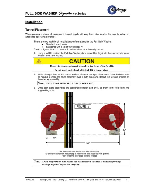
Shown in figures 1a and 1b are the floor dimensions for both configurations.
1) Using a forklift, position the Full Side Washer stand assembles (legs) into their appropriate tunnel
location (FIG 1a or FIG 1b).
Be sure to clamp equipment securely to the forks of the forklift.
Do not stand under load while fork lift is in operation.
2) While placing a level on the vertical surface of one of the legs, place shims under the base plate
as needed to make the stand assembly level in both directions. Repeat this leveling process on
the other leg assembly.
Note: SHIMS NOT SUPPLIED BY BELANGER, INC.
3) Once both stand assembles are positioned correctly and level, lag them to the floor using the
supplied lag bolts.
FIGURE 1a
84"
59"
166"
166" dimension is taken from the outer edge of base plates.
59" dimension is taken from the outer edge of the driver-side base plate to the inside guide rail
Heavy dotted lines show proper operating envelope
Note: Above image shown with booms and wash material installed to indicate operating
envelope required to function properly.
1MANUL856 Belanger, Inc. * 1001 Doheny Ct. * Northville, MI 48167 * Ph (248) 349-7010 * Fax (248) 380-9681 11