
Page 11 - Stanochny park
P. 11
METALWORKING EQUIPMENT METALWORKING EQUIPMENT
AND TOOLS AND TOOLS
widely used drives in CNC machines.
Horizontal gear hobbing machines. A similar approach is applicable to the range of
horizontal gear milling machines ø200 - 1250 mm. The basic model for the first three is the
ø320 mm machine, and for the remaining two - the ø800 mm machine. A distinctive feature
is the design of the workpiece headstock: in the first three, the spindle is mounted on rolling
bearings, and in the second on hydrostatic bearings. The design of the milling support is similar
to vertical machines.
Synchronous built-in electric motor
P=31,6 кWe, n=950(rpm)
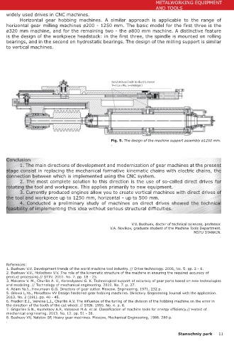
Fig. 5. The design of the machine support assembly ø1250 mm.
.
Conclusion
Fig. 4. Typical design of the machine table: a - ø200 mm, b - ø1250 mm.
1. The main directions of development and modernization of gear machines at the present
stage consist in replacing the mechanical formative kinematic chains with electric chains, the
with sizes up to 800 mm can be successfully designed with direct drives of workpieces and mills connection between which is implemented using the CNC system.
on engines of the 1FW6 or 1FE1 type (depending on the required speed). A 1250 mm machine 2. The most complete solution to this direction is the use of so-called direct drives for
requires installation of two parallel-running motors on the milling spindle to provide the required rotating the tool and workpiece. This applies primarily to new equipment.
torque (Fig. 5). 3. Currently produced engines allow you to create vertical machines with direct drives of
The design of the drives for other coordinates (moving the tool support, stand, turning the tool and workpiece up to 1250 mm, horizontal - up to 500 mm.
the support to the required angle) is not considered here, because they do not differ from the 4. Conducted a preliminary study of machines on direct drives showed the technical
Table 1. Parameters for selecting direct drives vertical hobbing machines feasibility of implementing this idea without serious structural difficulties.
parameter Max. workpiece diameter D V.V. Bushuev, doctor of technical sciences, professor.
200 320 500 800 1250 V.A. Novikov, graduate student of the Machine Tools Department.
Maximum module m, mm 4 6 8 10 12 MSTU STANKIN. .
Max. diameter of a worm mill 125 160 180 200 225
Dфр, mm
The angle of inclination of the 45 45 35 35 30
teeth, β, deg
Cutting speed V, m / min 25 25 22 22 20 References:
The value of the axial feed of the 4 4 3,5 3,5 3,5 1. Bushuev V.V. Development trends of the world machine tool industry. // Drive technology. 2006, No. 5. pp. 2 - 6.
2. Bushuev V.V., Molodtsov V.V. The role of the kinematic structure of the machine in ensuring the required accuracy of
cutter Sос, mm / rev. product processing.// STIN. 2010. No. 7. pp. 18 - 25.
Circular cutting reinforcement 4800 7200 7600 9500 11000 3. Makarov V. M., Churilin A. V., Korendyasev G. K. Technological support of accuracy of gear parts based on new technologies
and modeling. // Technology of mechanical engineering. 2010. No. 7. p. 27.
F2, H 4. Adam Ya.I., Hovumyan G.G. Directory of gear cutter. Moscow. Engineering, 1971, 232 p.
The moment on the mill Мфр, Нм 300 580 700 950 1200 5. Gilovoi L.Ya., Molodtsov VV Design hardened gear hobbing machines. Directory. Engineering Journal with the application.
2013. No. 2 (191). pp. 40 - 45.
Workpiece moment Мзаг, Нм 360 850 1300 2500 3800 6. Fradkin E.I., Vereina L.I., Churilin A.V. The influence of the tuning of the division of the hobbing machine on the error in
the direction of the tooth of the cut wheel. // STIN. 1995. No. 4. p. 8.
Max. cutter rotation frequency 600 500 400 300 250 7. Grigoriev S.N., Kuznetsov A.P., Volosova M.A. et al. Classification of machine tools for energy efficiency.// Herald of
nmax, rpm mechanical engineering. 2013. No. 12. pp. 51 - 56.
8. Bushuev VV, Naletov SP, Heavy gear machines. Moscow, Mechanical Engineering, 1986. 280 p.
.
10 Stanochniy park Stanochniy park 11