
Page 15 - Stanochny park
P. 15
METALWORKING EQUIPMENT METALWORKING EQUIPMENT
AND TOOLS AND TOOLS
In
Investigation of the stiffness and bearing vestigation of the stiffness and bearing
capacity of an HSK joint bythe method of y of an HSK joint bythe method of the spindle before termination 3 was
● the length of the front end of
capacit
simulation modelling
The cutting process creates a simulation modelling chosen minimally sufficient to maintain
complex spatial picture of the loading unchanged the stress-strain state of the
of the HSK joint by cutting forces and its author considered the possibility system, the pattern of deformations at the
mandrel fixing. As a rule, the axial of residual radial deformations only joints of the spindle and mandrel caused
component of the cutting force provides in a flat joint, between the flanges of by external loading and the action of the
clamping of the mandrel to the spindle the mating parts, and the occurrence clamping mechanism;
and does not interfere with the operation of axial displacements caused by the ● the magnitude and direction
of the connection; therefore, the radial action of pulling loads was not taken of the force (Fзаж) acting from the
component and the moment created into account. clamping mechanism to the inner flange
by it are of the greatest interest for Given the results obtained in [2], of the mandrel 4, correspond to the force
assessing the operational capabilities this approach should be considered developed by the clamping mechanism
of HSK. one-sided. To understand the physical phenomena in accordance with the recommendations
The failure of the HSK tool joint that lead to failure of the joint and the nature of the of ISO 12164-1: 2001 and ISO 12164-2: Taking into account the symmetry of the
occurs when the maximum permissible faults, it is necessary to study the behavior of the joint 2001; stress-strain state of the structure allows you to build
load is exceeded and is accompanied by at different radial loads applied at different distances ● the coefficient of friction at the an adequate mathematical model, while reducing
unacceptable movement of the mandrel from the flat ring joint. joints of the mandrel and spindle is taken its dimension by half. Accordingly, the magnitude
relative to the spindle, a significant Due to the fact that experimental observation equal to 0.2 (contact of steel surfaces in of external forces should be reduced by half, and
decrease in the joint rigidity during of the effects listed above is difficult, the study was the absence of lubrication); when analyzing the results, a reverse transition to
cutting, and the occurrence of residual conducted in the environment of finite element ● the stress-strain state of the the full structure was performed. The critical load
deformations. Signs of a starting failure modeling Simulation, integrated into the CAD system structure is symmetrical with respect to (Fкр), which determines the moment of loss of
may include: SolidWorks. The following describes the methodology the plane of application of the external performance, depends on both external factors (F
● radial movement of the mandrel for constructing mathematical models and processing radial load. and L), and from a combination of tolerances on the
flange relative to the spindle end results for the HSK-A40, HSK-A63 and HSK-A100 When constructing the finite element geometric dimensions of the connecting surfaces of
surface in contact with the shear load systems. model, the following simulation features the mandrel and spindle. The initial data for assessing
at the joint [1]; were used: the influence of the accuracy of manufacturing the
● to construct the mesh, finite mandrel and spindle on the value of Fкр connections
elements were used — tetrahedra with a were taken from GOST R 51547-2000 and GOST
second-order form function; R 51726-2001. Depending on the combination of
● joints were described by special tolerances of the connecting surfaces of the spindle
finite elements, taking into account the and mandrel, two extreme cases are possible:
possibility of mating surfaces coming out ● the conical part of the seat in the spindle
of contact and friction between them; is made along the lower boundary of the tolerance
● the sequence of application of field, the mandrel cone - along the upper boundary
forces - tightening the mandrel into the (hereinafter this combination is called a ‘‘tight‘‘fit);
spindle and the subsequent application ● the conical part of the seat in the spindle is
of radial load - is implemented using the made along the upper boundary of the tolerance
boundary condition ‘‘hot landing‘‘; field, the mandrel cone - along the lower
● geometric non-linearity of the boundary (hereinafter this combination is called a
model, arising due to the redistribution ‘‘weakened‘‘landing).
of contact pressures at the joints under The connecting surfaces of real joints have
the influence of radial force, is taken into shape deviations and roughness that affect the
a b account by the applied algorithm of ‘‘large distribution of loads in the structure and its rigidity.
displacements‘‘; In mathematical models, the shape is perfect,
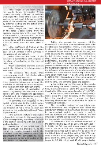
Fig. 1. The design model of the connection ‘‘spindle - tool holder‘‘.. ● the symmetric nature of the solution and the surfaces are absolutely smooth, and the
is taken into account by the appointment influence of errors can be taken into account due to
● axial movement of the flange relative When choosing a design scheme (see Fig. 1, a), of the corresponding boundary conditions the appropriate combination of tolerances.
to the end surface of the spindle in the following features of the functioning of structural in the section coinciding with the plane of In accordance with the recommendations of
contact with the force pulling the elements were taken into account: load application; the standards ISO 12164-1: 2001 and ISO 12164-
mandrel from the spindle [2]. ● the ability to open the joints of the spindle 1 ● reduction of the radial load (F) 2: 2001, the flat ring joint should absorb at least
It was proposed in [1] to evaluate and mandrel 2 under load; applied through the shoulder (L) to the 75% of the force from the clamping mechanism.
the maximum permissible load on the ● the nature of the contact interaction at the end of the mandrel is carried out by the Calculations carried out for cones 40, 63 and 100 of
tool joint with a statically indeterminate joints formed by the mandrel and the spindle depends boundary condition ‘‘distance loads‘‘- the the HSK-A joint showed that with a ‘‘tight‘‘fit, only
basing system by the occurrence of on a combination of their sizes within the tolerance assignment of the corresponding forces 49%, 42% and 62%, respectively, perceive a ring
residual deformations in the joints fields; and moments in the grid nodes at the joint, and 84%, 89% and 83% of Fzag respectively
between the mating parts. However, front end of the mandrel. (equal to 6.8 kN, 18 kN and 45 kN, respectively).
14 Stanochniy park Stanochniy park 15