Page 18 - Stanochny park
P. 18

METALWORKING EQUIPMENT                                                                                                                                                                                   METALWORKING EQUIPMENT
        AND TOOLS                                                                                                                                                                                                AND TOOLS
               The  contribution  of  the  rotation  of  the  mandrel  relative  to  the  spindle in  its  radial
        displacements can be estimated by the expression:                                                                                                                                             the  massive  cylindrical part  of  the
                                                                                                                                                                                                             mandrel  and  the  spindle,  in
                                                                                                                                                                                                                 the  region  of  the  control
                                                                                                                                                                                                                 platform 1, which restrained
                                                                                                                                                                                                                 the  volumetric deformation
                                                                                                                                                                                                              of  the  spindle,  the  radial

               A quantitative analysis carried out using this dependence showed the insignificance of this                                                                                               movements of the control platform
        contribution for all considered joint sizes and load application options.                                                                                                                      2 of the spindle sharply increase. In
        A detailed description and analysis of the nature of deformations and physical processes in the                                                                                                turn, the increase in the movement
        considered tool joints occurring as a result of the action of the set of external loads specified                                                                                              of the control platform 1, caused by
        above is given on the example of the HSK-A63 joint.                                                                                                                                               the increase in radial load, slows
                                                                                                                                                                                                             down.  The  massive  cylindrical
                                                                                                                                                                                                             part  of  the  mandrel  carries
                                                                                                                                                                                                             with  it the  spindle material
                                                                                                                                                     a                                  b                 interacting  with it.  The  cross
                                                                                                                                 Fig. 4. Pressure distribution on the                    section of the spindle in the region of the flat
                                                                                                                                 contacting surfaces of the mandrel and                  end  assumes  an  oval shape,  as  well  as  the
                                                                                                                                 spindle at various values of radial force:
                                                                                                                                 a) - 0 kN (clamp); b) - 5 kN.                           cross section of the spindle, and in the region of
                                                                                                                                                                                         control sites 3 and 4 at loads exceeding 4 kN.
                                                                                                                                        The deformation of the conical part of the mandrel contributes to the offset of the mandrel
                                                                                                                                 relative to the spindle. Figure 5, b illustrates the radial movements of the control pads 3 and 4
                                                                                                                                 of the mandrel. In the initial section, up to about 3 kN, the curves are parallel, i.e. the shank
                                                                                                                                 is practically not deformed under the action of radial load. With increasing radial deformations
                                                                                                                                 (ovality) of the spindle, the deformations of the shank caused by the clamping force of the
                                                                                                                                 mandrel decrease, and the curves diverge. Subsequently, the partial opening of the conical joint
                                                                                                                                 due to deformations of the shank and spindle leads to the inclination of the mandrel, which
                                                                                                                                 corresponds to a change in the direction of movements of platforms 3 and 4 in Fig. 5, b.
                                                                                                                                        As the flat unfolds, the load on the conical joint increases, which partially opens (see the
                                                                                                                                 movement of the sites 4 in Fig. 5, b) when exceeded 5 kN radial force.
                                   a                                                      b                                             The nature of the curves in Fig. 5 allows us to conclude that for radial forces exceeding
                                                                                                                                 Fкр, the relative radial displacement of the mandrel and spindle does not occur in the form of
                                                                                                                                 ‘‘stall‘‘, as stated in [1], but is the result of complex spatial deformations of the mandrel and
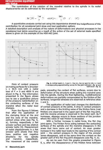
                                                         Fig. 3. Critical loads (1, 3 and 5 - Fкр (x), Fкр (y) and Fcr (θ); 2, 4 and
               Plots of  contact pressure               6 corresponding approximating curves for the joint HSK-A63 - fig. а) and   spindle, which cannot be taken into account using analytical models. Based on the calculation
        on mating surfaces for a shoulder                                                                HSK-A100 - fig. b)      results, the following conclusions can be drawn:
        L  =  94.5  mm  with  a  radial           pads, preceding the contact of flat surfaces, occurs due to                           ●  when  using  the  HSK  joint,  it
        load  of  F  =  0  and  4500  N  are      deformation of the structure when pulling the mandrel cone                     retains its operational properties for all
        shown in Fig. 4. The information          into the spindle. During the final tightening, multidirectional                considered variants of radial loads not
        presented  in  the  figure  allows        deformations are partially compensated by the friction of flat                 exceeding a certain critical value. Joint
        you to see a qualitative picture          surfaces; tangential stresses are observed at reference sites                  deformations  in this load range  are
        of the pressure redistribution on         1 and 2.                                                                       commensurate with calculation errors.
        the  contacting  surfaces  of  the               The application of radial load changes the distribution                 In  carrying  out  practical  calculations,
        mandrel  when the  radial load            of contact pressure at the joints. A drop in contact pressure                  the  compliance  of  the  joints can  be
        changes.                                  and a decrease in the limiting value of the friction force (rest               neglected;
               From the figures it follows        friction) are observed in the upper part of the flat ring joint,                      ● when the load increases above
        that  after  the  application of          and the reverse process is observed in the lower part. As F                    a  certain  critical value,  axial,  radial
        the  clamping force  at the  end          increases, slippage occurs in those sections of the junction                   and  angular  displacements  of  the
        and  the  cone  of  the mandrel,          where the value of rest friction is exceeded.                                  mandrel  appear  due to the  pulling                           a                                b
        contact areas arise (see Fig. 4,                 With  a  further  increase  in  radial  force,  the  flat  ring         of  the mandrel and  spindle and  their                   Fig. 5. Radial movement of control sites: a) - at the end and cone
        a),  forming  respectively  a  flat       joint opens. The friction force acting between the contacting                  volumetric      deformations.       With     a                       spindle; b) - on the cone of the spindle and mandrel.
        annular surface and two distinct          surfaces of the spindle and the mandrel disappears in the                      further increase in load, the compound
        annular belts [3]. Measurement            areas  that  have  come  out  of  contact.  An  even  greater                  loses its operational properties. Failure,
        of radial displacements in a flat         increase in the radial load leads to the opening of the conical                which is necessarily preceded by the disclosure of a flat joint, is accompanied by a sharp increase
        annular  joint shows that  they           joint — the  contact  pressure  in the  region  of  the  annular               in the compliance of the mandrel-spindle joint in the axial and radial directions;
        have positive and negative                zones disappears, and at the same time the contact on the                             ● in none of the load application variants, there was no complete slippage between the
        directions     for     the    spindle     greater part of the flat ring joint disappears (see Fig. 4, b).                mandrel and the spindle on the entire surface of the flat ring joint. Slip on a part of the surface
        and      mandrel,       respectively.            As can be seen from the graphs presented in Figure                      of the annular joint does not significantly affect the operational properties of the joint;
        The  movement  of  the  control                                                                                                 ● the distance from the end face of the spindle to the point of application of the radial
                                                  5, a, after the disappearance of the friction force between                    load (L), along with the dimensions of the joint, is the most important parameter characterizing

       18   Stanochniy park                                                                                                                                                                                                  Stanochniy park      19
   13   14   15   16   17   18   19   20   21   22   23