
Page 17 - Stanochny park
P. 17
METALWORKING EQUIPMENT METALWORKING EQUIPMENT
AND TOOLS AND TOOLS
Consequently, the choice of a ‘‘weakened‘‘landing at the conical junction provides a better The displacements measured on pads 1 and Estimates of the critical radial force Fкр made
adequacy of the mathematical model. 2 on the flange of the mandrel (similar areas are on the basis of the analysis of the axial, radial
The calculations were carried out with the values of the offset equal to D, 1,5D, 2D, 2,5D highlighted on the end of the spindle) are used in and angular displacements of the mandrel for
3D, and 3,5D. The choice of the shoulder L = D was made taking into account the fact that with the future to assess the angle of rotation of the different values of the tool overhang and the
a minimum shoulder of application of the load at the moment the ‘‘pulling‘‘of the tool begins, mandrel relative to the spindle, after applying the size of the connection are shown in Figures
the cutting force is maximum, and smaller overhangs are impossible in real tool and mandrel load and controlling slippage along the surface 2, d and 3. In the figures, the curves Fкр (x)
designs (see ISO 12164-1: 2001, ISO 12164 -2: 2001). of the flat joint. The displacements measured on and Fкр (θ) can be approximate accurately
The calculation results are displacements caused by deformation of the spindle and pads 3 and 4 on the mandrel cone (similar sites by simple dependency
mandrel and slippage at the joints of the joint, reactions in the joint elements, pressure plots are highlighted on the spindle cone) are used
on mating surfaces. in the future to evaluate the extension of the Fкр (a’) = 1000 [МHSK]/ a’ (2),
The magnitude of the reaction forces was measured directly on the end and conical surfaces mandrel from the spindle. To calculate the axial
of the mandrel and spindle. The magnitude of the radial, axial, and angular displacements of (δx) and radial (δr) movements and the angle of where [МHSK] is the bending moment
the mandrel relative to the spindle was determined by measuring the absolute displacements rotation of the mandrel (θ) relative to the spindle, permissible in axial and angular displacements
of the nodal points of the finite element model at control sites 1–4, which were highlighted on the following dependences were used: in the joint HSK, Нм; a ‘is the distance from
the mating surfaces of the mandrel and spindle (see Fig. 1, b). the end face of the spindle to the cutting
δx = δHx - δSx (1,а), zone (tool overhang), mm. The calculated
[МHSK] values for the compounds for the
δr = δHr - δSr (1,b) and compounds are shown in Table 1.
с) Table 1. The ultimate load in the connection HSK.
Here: δHx, δHr and δSx, δSr are the average HSK - A40 HSK - A63 HSK - A100
values of the displacement of the nodal points of [МHSK] 80 320 1280
the finite element model in the axial and radial [F HSK] 420 880 3490
directions, measured on the mandrel flange and [М’HSK] 62 255 690
the spindle end; δHx1, δHx2 and δSx1, δSx2 -
average values of the nodal displacement axial
displacement points, measured at control pads
1 and 2 of the mandrel and spindle; Dm is the The relationship between the axial
diameter passing through the centers of the and angular movements of the mandrel
control sites (see Fig. 1, a). relative to the spindle is given by a simple
The graphical dependences of the linear expression
and angular displacements of the mandrel
relative to the spindle on the radial loads obtained
a b using expressions (1) for different values of the
outreach of the HSK-A40 connections are shown
in Figures 2a), b), c), respectively. An analysis
of the linear and angular displacements of the The error of this approximation does
mandrel relative to the spindle (Figs. A - c) shows not exceed 10% for all load application
that in the lower part of the loading range their variants and all considered joint sizes. The
value is very small, and the radial stiffness of the curves Fкр(y) can be approximated fairly
joint is very large. accurately by the dependence
In practical calculations, the connection can
be considered absolutely rigid. The similar nature Fкр (a’) = [FHSK] + 1000 [М’HSK]/ a’ (3),
of the movements in the HSK-A63 and HSK-A100
compounds allows us to conclude that there is where [FHSK] is the additional shear
a single qualitative picture of the behavior of load, Н; [M’HSK] - permissible radial
HSK compounds during their perception of radial displacement bending moment in the joint
loads, regardless of the size of the connection. HSK, Нм. The values of [FHSK] and [M’HSK]
An increase in the load above a certain critical value calculated during the approximation for the
leads to axial, radial and angular movements of the compounds in question are shown in Table
mandrel due to the pulling of the mandrel from the 1.
spindle and their volumetric deformations. With a The more complex form of expression
c d further increase in load, the compound loses its (3) and the nature of the graphs of radial
operational properties. The current situation can displacements allow us to make an
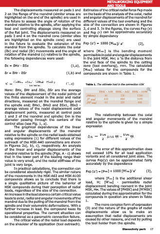
Fig. 2. Movement of the mandrel of the HSK-A40 joint relative to the spindle: be considered as a parametric connection failure. assumption that radial displacements are
a) - δx, b) - δr, c) - θ, d) - critical loads (1, 3 and 5 - Fкр(x), Fкр (y) and Fкр (θ); The critical value of the radial load depends caused by other reasons, and not by pulling
2, 4 and 6 are the corresponding approximating curves). the tool holder from the spindle.
on the shoulder of its application (tool outreach).
16 Stanochniy park Stanochniy park 17