Page 22 - Stanochny park
P. 22

INNOVATIVE TECHNOLOGY                                                                                                                                                                                     INNOVATIVE TECHNOLOGY

        processing time on the CNC machine.
               Given  the  complex  shape  and
        large  dimensions  of  the  workpieces,  it
        was decided to scan them directly at the
        customer’s enterprise  using a  portable
        coordinate  measuring  machine  (CMM)
        СimСore  INFINITE  2.0,  equipped  with  a                                                                                                                                                Fig. 2. Point cloud of one of the scanned blanks
        ScanWorks laser scanner. With its help, a                                                                                                                                                 (top) and its corresponding theoretical CAD model.
        3D  scan  of  three  blanks was  made.  The
        scanning process was carried out in several
        KIM  reinstallations necessary  for  access
        to product elements  from  all sides. As  a
        result, up to six files were obtained for each
        blank  describing its shape  using  clouds
        of  scanned  points in various  coordinate
        systems.  Then,  using the  PowerINSPECT
        CAI  system (also developed  by  Delcam),


                                                                                                                                        Fig. 3. Examples of a triangulated 3D model blanks.


                                                                                                                                                                                   Fig. 4. Solid CAD model of one from blanks.


                                                                                                                                                                                                                      Fig. 5. The process of
                                                                                                                                                                                                                      combining CAD model
                                                                                                                                                                                                                      theoretical details with a
                                                                                                                                                                                                                      real model blanks to achieve
                                                                                                                                                                                                                      uniform allocation allowance.


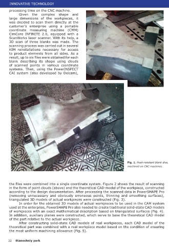
                                                                                               Fig. 1. Heat-resistant blank dies,      The use of reverse engineering
                                                                                               machined on CNC machines.        tools implemented in Delcam software
                                                                                                                                allowed  us  to  solve  quickly  the
                                                                                                                                problem  of  constructing  solid-state
                                                                                                                                CAD  models  of  actual  workpieces
                                                                                                                                in a short time. This, in turn, made
        the files were combined into a single coordinate system. Figure 2 shows the result of scanning                          it  possible  for  programmers  and  technicians
        in the form of point clouds (above) and the theoretical CAD-model of the workpiece, constructed                         to distribute  evenly the  machining  allowance
        according to the design documentation. After processing the scanned data in PowerSHAPE Pro                              and  precisely  set  the  boundaries  of  the  zones  of
        (removing unnecessary  and  obviously erroneous  points,  thinning and  smoothing  surfaces),                           guaranteed  safe  tool movements  at  accelerated
        triangulated 3D models of actual workpieces were constructed (Fig. 3).                                                  feeds. Thanks to the work done, the efficiency of
               In order for the obtained 3D models of actual workpieces to be used in the CAM system                            control  programs  has  significantly  increased  and
        used at the enterprise, PowerSHAPE Pro also needed to create traditional solid-state CAD models                         the likelihood of breakdown of tools and equipment
        of workpieces with an exact mathematical description based on triangulated surfaces (Fig. 4).                           has decreased.
        In addition, auxiliary planes were constructed, which serve to base the theoretical CAD model
        of the part relative to the actual workpiece.
               After  constructing  solid-state CAD  models  of  real  workpieces,  each  CAD  model of  the
        theoretical part was combined with a real workpiece model based on the condition of ensuring
        the most uniform machining allowance (Fig. 5).                                                                                                                                                    A.G. Bazhin, I.A. Pechenkin, V.A. Puzanov.
                                                                                                                                                                                                                   Izhevsk State Technical University.

       22   Stanochniy park                                                                                                                                                                                                  Stanochniy park      23
   17   18   19   20   21   22   23   24   25   26   27