
Page 8 - Stanochny park
P. 8
METALWORKING EQUIPMENT METALWORKING EQUIPMENT
AND TOOLS AND TOOLS
A distinctive feature of the basic models Fig. 1. General drives innings.
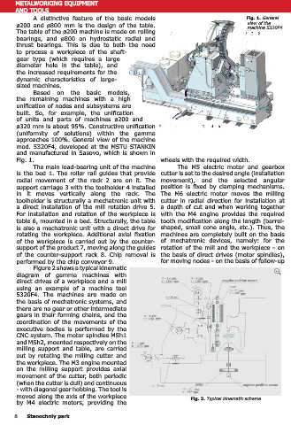
ø200 and ø800 mm is the design of the table. view of the Figure 3 shows a typical design of a caliper with direct drive rotation of the cutter for
machine 5320F4.
The table of the ø200 machine is made on rolling machines ø200 - 800 mm on the example of a machine 5320F4. The rotor 1 of the electric
bearings, and ø800 on hydrostatic radial and motor is mounted on the spindle 2, in the cone of which a mandrel 3 with a mill is installed 4.
thrust bearings. This is due to both the need The stator 5 of the engine is fixed in the caliper body 6, which moves drive 7 along the slideways
to process a workpiece of the shaft- relative to the rotary housing 8 mounted in the slide. This produces a tangential feed of the
gear type (which requires a large tool. When cutting without tangential movement of the cutter, the housing 6 is secured by the
diameter hole in the table), and Belleville springs of the clamping mechanism 9. To change the cutter, it is envisaged to move
the increased requirements for the the counter-holder 10 from the hydraulic cylinder and secure it in the working position clamping
dynamic characteristics of large- mechanism 11.
sized machines. The control of the angular position of the cutter spindle is carried out by the sensor
Based on the basic models, 12, and the required relationship between the angle of rotation of the cutter and the table is
the remaining machines with a high implemented using the CNC system.
unification of nodes and subsystems are
built. So, for example, the unification
of units and parts of machines ø200 and
ø320 mm is about 95%. Constructive unification
(uniformity of solutions) within the gamma
approaches 100%. General view of the machine
mod. 5320F4, developed at the MSTU STANKIN
and manufactured in Sasovo, which is shown in
Fig. 1. wheels with the required width.
The main load-bearing unit of the machine The M5 electric motor and gearbox
is the bed 1. The roller rail guides that provide cutter is set to the desired angle (installation
radial movement of the rack 2 are on it. The movement), and the selected angular
support carriage 3 with the toolholder 4 installed position is fixed by clamping mechanisms.
in it moves vertically along the rack. The The M6 electric motor moves the milling
toolholder is structurally a mechatronic unit with cutter in radial direction for installation at
a direct installation of the mill rotation drive 5. a depth of cut and when working together
For installation and rotation of the workpiece is with the M4 engine provides the required
table 6, mounted in a bed. Structurally, the table tooth modification along the length (barrel-
is also a mechatronic unit with a direct drive for shaped, small cone angle, etc.). Thus, the Fig. 3. The design of the machine support assembly ø200 - 800
rotating the workpiece. Additional axial fixation machines are completely built on the basis
of the workpiece is carried out by the counter- of mechatronic devices, namely: for the Figure 4 shows a typical design of a does not require a change in the design
support of the product 7, moving along the guides rotation of the mill and the workpiece - on machine table ø200 - 500 mm with direct drive of the nodes of the drives for rotating the
of the counter-support rack 8. Chip removal is the basis of direct drives (motor spindles), for rotating spindle 1 with a workpiece installed tool and the workpiece. In machines of
performed by the chip conveyor 9. for moving nodes - on the basis of follow-up in it. The rotor 2 of the electric motor is mounted the traditional layout, the number of teeth
Figure 2 shows a typical kinematic on the glass 3, which is connected by a coupling of the dividing worm wheel changes with
diagram of gamma machines with 4 to the spindle. The stator of the motor 5 is increasing accuracy. It also increases the
direct drives of a workpiece and a mill кWe кWe rpm angular position sensor fixed on the fixed part of the table. The control level of unification of parts and assemblies
rpm
using an example of a machine tool кWe of the angle of rotation of the spindle is carried in the gamut of machines.
5320F4. The machines are made on rpm out by the feedback sensor 6. The workpiece is The required parameters of direct
the basis of mechatronic systems, and clamped at the end of the device (not shown in drives for rotating the tool and workpiece
there are no gear or other intermediate Fig. 4) by the hydraulic cylinder 7. are given in table. 1. To determine these
gears in their forming chains, and the кWe Structurally, machine tables ø800 - parameters, the forces and moments
coordination of the movements of the rpm 1250 mm differ only in the diameter of the were calculated according to the cutting
executive bodies is performed by the faceplate 8, on which the workpiece is fixed, conditions selected from literary sources [4].
CNC system. The motor spindles MSh1 and the faceplate supports, which are used as The calculation was carried out for various
and MSh2, mounted respectively on the кWe hydrostatic closed circular guides 9 and a radial types of wheels when using high-speed and
milling support and table, are carried rpm bearing 10. carbide tools with maximum modules and
out by rotating the milling cutter and As can be seen from Figures 3, 4, the workpiece diameters.
the workpiece. The M3 engine mounted designs of the most critical units when using Data on the machines of foreign firms
on the milling support provides axial direct drives become very rigid, the kinematic of similar purpose were also analyzed. To
movement of the cutter, both periodic chains are as short and gapless as possible. It analyze the feasibility of implementing the
(when the cutter is dull) and continuous MSh2 angular position sensor should be noted that changing the accuracy of required drive parameters (Table 1), the
- with diagonal gear hobbing. The tool is rpm the machines (transition from class to class) is currently manufactured Siemens engines
кWe
moved along the axis of the workpiece Fig. 2. Typical kinematic scheme. possible only by replacing the feedback sensors were studied.
by M4 electric motors, providing the of rotation of the tool and the workpiece and The analysis showed that machines
8 Stanochniy park Stanochniy park 9