
Page 110 - eProceeding for IRSTC2017 and RESPeX2017
P. 110
Anwar / JOJAPS – JOURNAL ONLINE JARINGAN COT POLIPD
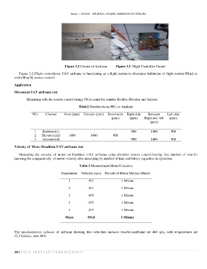
Figure 3.1 Creator of Airframe Figure 3.2 Flight Controller Circuit
Figure 3.2.Flight controlleron UAV airframe is functioning as a flight system to determine habitation of flight motion.Which is
controlling by remote control.
Application
Movement UAV airframe test
Measuring with the remote control trinigy 5X.to count the number Rudder, Elevator and Aileron
Table2 NumberchannelRC on Airplane
NO. Channel Over (ppm) Upstairs (ppm) Downstairs Right side Between Left side
(ppm) (ppm) Right and left (ppm)
(ppm)
1 Rudder(ch1) - - - 900 1400 900
2 Elevator(ch2) 1800 1400 900 - - -
3 Aileron(ch4) - - - 900 1400 900
Velocity of Motor Brushless UAV airframe test
Measuring the velocity of motor on brushless UAV airframe using throtthel remote control.Testing into number of time.To
knowing the comparatively of motor velocity after measuring by number of time and battery capasities in operation.
Table 3 Measurement MotorVelocities
Experiment Velocity (rpm) Periode of Motor Motion (Menit)
1 417 1 Minute
2 447 1 Minute
3 470 1 Minute
4 475 1 Minute
5 475 1 Minute
Mean 456.8 1 Minute
The speedometeron software of airframe showing that velocities onmotor brushlessairframe are 460 rpm, with temperatures are
42,13celcius, onto 46%.
108 | V O L 8 - I R S T C 2 0 1 7 & R E S P E X 2 0 1 7