
Page 1861 - Foton Workshop Manual - Aumark (BJ1099)
P. 1861
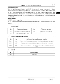
CIRCUIT - SYSTEM SCHEMATIC DIAGRAM                            61-71

                 System description:
                 With the ignition switch located at ON/ST, the current is output into the pin 3 of the
                 reversing lamp relay R02 through the fuse F31 in the internal fuse box, then output from
                 the pin 5 of reversing lamp relay into the pin 3 of left rear reversing lamp and pin 3 of right    61
                 rear reversing lamp; after passing through the reversing lamp filament, and the pin 1 of left
                 rear reversing lamp and pin 1 of right rear reversing lamp are earthed. The reversing lamp
                 is activated.
                  Repair prompt
                 • R02 Reversing lamp relay
                  3 - 5:activated when the transmission control mechanism is located at the reverse gear
                 position.


                     :Parts Location

                     No.             Reference harness               No.             Reference harness

                     C05       Front wall instrument wiring harness   N05         Rear bumper wiring harness

                     N02          Rear bumper wiring harness

                     :Connectors Among The Harness


                     No.        No.                    Reference harness(Connector location)

                    B301        D301       Frame wiring harness and rear bumper wiring harness (Beneath rear frame)
                    B201        D301         Frame wiring harness and floor wiring harness (Beneath the driver seat)

                                           Front wall instrument wiring harness and floor wiring harness (Beneath left A
                    C301        D201
                                                                          pillar)


                     :Ground

                     No.                                      Ground position

                     D51                                          Left D pillar


                                                                                                     Page 1861