
Page 2568 - Foton Workshop Manual - Sauvana
P. 2568
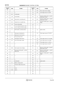
62-516                       DIAGNOSIS-ENGINE CONTROL SYSTEM


             Terminal   Color           Function                Terminal   Color           Function
               No.                                                No.
               15       —      —                                  62       W-P    Rear oxygen sensor voltage +
               16       —      —                                  63       O-B    Front oxygen sensor I.A.LUIP1
               17      Br-R    Air flowmeter                       64       —      —

                                                                                  Electronic throttle pedal  2 position
               18       L-W    Air flowmeter                       65       Y-L
                                                                                  signal power source
                                                                                  Electronic throttle pedal  1 position
               19      Gr-W    Brake switch ( normally open )     66       W-Y
                                                                                  signal power source
                                                                                  Electronic throttle pedal  1 position
               20       G-O    Request from air conditioning      67       L-O    signal

               21       Y-B    Cruise setting switch              68       —      —
               22        V     Cruise setting deceleration switch   69     —      —
               23       P-B    Cruise setting acceleration switch   70     —      —

               24        O     Brake switch ( normally-closed )   71       Lg     Ignition switch
               25       —      —                                  72       —      —
               26       Y-V    High-speed of electrical fan       73       L-R    Front oxygen sensor O.T.HOSP1

               27       V-Y    High-speed of electrical fan       74       —      —
               28        V     Oil pump relay control             75       —      —
               29       L-B    Rearoxygen sensor heater -         76       R-O    Front oxygen sensor O.V.LSUVM1
               30       R-Y    ECU normal power supply            77       G-B    Front oxygen sensor I.A.LUUN1
               31       —      —                                  78      Gr-W    Front oxygen sensor I.A.LSUIAI

               32       —      —                                  79       O-B    Front oxygen sensor I.A.LUIP1
               33       —      —                                  80       —      —
                                                                                  Electronic throttle pedal  2 position
               34       W-B    Rear oxygen sensor voltage -       81       Y-L
                                                                                  signal power source
               35       L-P    Electronic throttle pedal  1 position   82  W-Y    Electronic throttle pedal  1 position
                               signal GND                                         signal power source
                                                                                  Electronic throttle pedal  1 position
               36       —      —                                  83       L-O
                                                                                  signal
               37       —      —                                  84       —      —
               38       —      —                                  85       —      —
               39       —      —                                  86       —      —
               40        L     Air flowmeter                       87       Lg     Ignition switch

               41       Br     Medium voltage switch              88       —      —
               42        V     Electronic water pump control      89       —      —
               43       —      —                                  90       —      —
               44       L-Y    CAN-L                              91       —      —

               45       R-W    CAN-H                              92       —      —
               46       —      —                                  93       —      —
               47       —      —                                  94       —      —


                                                                                                     Page 2568