
Page 2634 - Foton Workshop Manual - Sauvana
P. 2634
62-582 DIAGNOSIS-ENGINE CONTROL SYSTEM
5. Check the signal circuit of the electronic accelerator pedal
(a). Ignition switch: LOCK。
(b). Disconnect the battery negative cable.
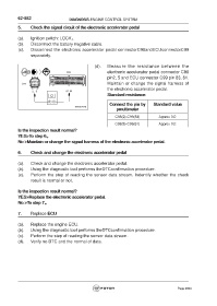
(c). Disconnect the electronic accelerator pedal connectorC98andECUconnectorC99
separately.
(d). Measure the resistance between the
electronic accelerator pedal connector C98
pin2, 5 and ECU connector C99 pin 83, 61.
Maintain or change the signal harness of
the electronic accelerator pedal.
Standard resistance:
Connect the pin by Standard value
pmultimeter
C98(2)-C99(83) Approx 0Ω
C98(5)-C99(61) Approx 0Ω
Is the inspection result normal?
YES>To step 6。
No >Maintain or change the signal harness of the electronic accelerator pedal.
6. Check and change the electronic accelerator pedal
(a). Check and change the electronic accelerator pedal.
(b). Using the diagnostic tool performs theDTCconfirmation procedure.
(c). Perform the step of reading the sensor data stream. Indentify whether the check
result is normal or not.
Is the inspection result normal?
YES>Replace the electronic accelerator pedal.
No >To step 7。
7. Replace ECU
(a). Replace the engine ECU.
(b). Using the diagnostic tool performs theDTCconfirmation procedure.
(c). Perform the step of reading the sensor data stream.
(d). Verify no DTC and the normal of data.
Page 2634