
Page 2633 - Foton Workshop Manual - Sauvana
P. 2633
DIAGNOSIS-ENGINE CONTROL SYSTEM 62-581
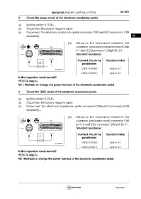
3. Check the power circuit of the electronic accelerator pedal.
(a). Ignition switch: LOCK。
(b). Disconnect the battery negative cable.
(c). Disconnect the electronic accelerator pedal connector C98 and ECU connector C99
separately. 62
(d). Measure the resistance between the
electronic accelerator pedalconnectorC98p
in1,4andECUconnector C99pin82, 81 .
Standard resistance:
Connect the pin by Standard value
pmultimeter
C98(1)-C99(82) Approx 0Ω
C98(4)-C99(81) Approx 0Ω
Is the inspection result normal?
YES>To step 4。
No > Maintain or change the power harness of the electronic accelerator pedal.
4. Check the GND circuit of the electronic accelerator pedal.
(a). Ignition switch: LOCK。
(b). Disconnect the battery negative cable.
(c). Disconnect the electronic accelerator pedal connectorC98andECUconnectorC99
separately.。
(d). Measure the resistance between the
electronic accelerator pedal connector C98
pin1, 6 and ECU connector C99 pin 35, 11.
Standard resistance:
Connect the pin by Standard value
pmultimeter
C98(3)-C99(35) Approx 0Ω
C98(6)-C99(11) Approx 0Ω
Is the inspection result normal?
YES>To step 5。
No >Maintain or change the power harness of the electronic accelerator pedal.
Page 2633