
Page 2628 - Foton Workshop Manual - Sauvana
P. 2628
62-576 DIAGNOSIS-ENGINE CONTROL SYSTEM
Is the inspection result normal?
YES>To step 3。
No >Maintenance related faults.
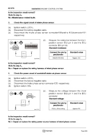
3. Check the signal circuit of intake phase sensor.
(a). Ignition switch: LOCK。
(b). Disconnect the battery negative cable.
(c). Disconnect the intake phase sensor connectorE52andthe ECUconnectorE01
respectively.
(d). Measure the resistance between the inlent
position sensor E52 pin 2 and the ECU
connector E01 pin 53.
Standard resistance:
Connect the pin by Standard value
pmultimeter
E52(2)-E01(53) Approx 0Ω
Is the inspection result normal?
YES>To step 4。
No > Repair or replace the wiring harness of inlent phase sensor.
4. Check the power circuit of crankshaft intake air phase sensor
(a). Ignition switch: LOCK。
(b). Disconnect the battery negative cable.
(c). Disconnect the intake phase sensor connector E52 respectively.
(d). Ignition switch: ON。
(e). Measure the voltage between the inlent
position sensor E52 pin 1 and the ECU
connector.
Standard voltage:
Connect the pin by Standard value
pmultimeter
E52(1)-Grounding Approx 5V
Is the inspection result normal?
YES>To step 5。
No > Repair or replace the wiring power source harness of inlent phase sensor.
Page 2628