
Page 2627 - Foton Workshop Manual - Sauvana
P. 2627
DIAGNOSIS-ENGINE CONTROL SYSTEM 62-575
Diagnosis Procedure
Notice:
• Before performing a diagnosis, ensure that the engineECUandthe VVTvalve are properly
connected.
• Before performing a diagnosis and testing, refer to circuit diagrams and component
information. 62
• Before performing the test, check whether the connector pins are ruptured, loosened or
corroded, to ensure proper contact of pin.
• If the connection is good, check the signal voltage of the sensor as moving the connector
and wiring harness. If a fault occurs, the corresponding voltage value display will
changeon the diagnostic tool.
△ PROMPT:
Intake phase sensor and exhaust phase sensor was inspected in the same way as the
inspection of the intake phase sensor for an exampl.
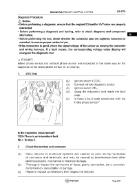
1. DTC Test
(a). Ignition switch: LOCK。
(b). Connect vehicle diagnostic device.
(c). Ignition switch: ON。
(d). Using the diagnostic tool reads the fault
code.
(e). Is there a fault code associated with the
intake phase sensor?
fuwx62176
Is the inspection result normal?
YES>There is an intermittent fault.
No > To step 2.
2. Check the terminal and connector
(a). Many failures in electrical systems are caused by poor wiring harnesses
of connector and terminals, and may be caused by interference from other
electricalsystems, mechanical or chemical damage.
(b). Thoroughly inspect the connectors of loose, poorly connection, bent, corrosion,
contamination, deterioration or damage.
(c). Repair or replace as necessary, then inspect the vehicles.
Page 2627