
Page 2622 - Foton Workshop Manual - Sauvana
P. 2622
62-570 DIAGNOSIS-ENGINE CONTROL SYSTEM
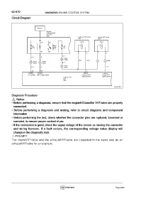
Circuit Diagram
Battery
Engine
compartment
fuse box
A40
Exhaust VVTvalve Intake VVTvalve
E07 E06
85 30
Main
F5 relay F24
10A 15A
R15
86 87
1 2 1 2
Br-Y
R-Y P
16 A302
C202 W-R Lg-R 7 2 E06
A301 A304
22 4 Br-Y
C201 C204
C018
R-Y P 4 E101 L-R
30 69 5
C99 C99 E01 E01
ECU power Main relay control Exhaust VVT Intake VVT
valve control valve control
Engine ECU
E01
C99
fuwx62025
Diagnosis Procedure
Notice:
• Before performing a diagnosis, ensure that the engineECUandthe VVTvalve are properly
connected.
• Before performing a diagnosis and testing, refer to circuit diagrams and component
information.
• Before performing the test, check whether the connector pins are ruptured, loosened or
corroded, to ensure proper contact of pin.
• If the connection is good, check the signal voltage of the sensor as moving the connector
and wiring harness. If a fault occurs, the corresponding voltage value display will
changeon the diagnostic tool.
△ PROMPT:
The intakeVVTvalve and the exhaustVVTvalve are inspected in the same way as an
exhaustVVTvalve for an example.
Page 2622