
Page 2624 - Foton Workshop Manual - Sauvana
P. 2624
62-572 DIAGNOSIS-ENGINE CONTROL SYSTEM
Is the inspection result normal?
YES>To step 4。
No >Maintenance related faults.
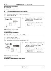
4. Check the power circuit of exhaust VVT valve
(a). Disconnect the exhaust VVT valve connector E07.
(b). Ignition switch: ON。
(c). Measure the voltage to earth of the
exhaustVVTvalve connectorE07pin1 .
Standard voltage:
Connect the pin by Standard value
pmultimeter
E07(1)-Grounding battery voltage
Is the inspection result normal?
YES>To step 5。
No >Fix or change the harness.。
5. Check the control circuit of exhaustVVTvalve
(a). Ignition switch: LOCK。
(b). DisconnectECUconnectorE01.
(c). Disconnect the exhaustVVTvalve connectorE07.
(d). Measure the resistance between the
exhaust VVT valve connector E07 pin2
and the ECU connector E01 pin5.
Standard resistance:
Connect the pin by Standard value
pmultimeter
E07(2)-E01(5) Approx 0Ω
Is the inspection result normal?
YES>To step 6。
No >Repair or replace the faulty wiring harness.
Page 2624