Page 2247 - Foton Workshop Manual - Tunland (AT)
P. 2247
WIRING - SYSTEM CIRCUIT DIAGRAM                             71-45


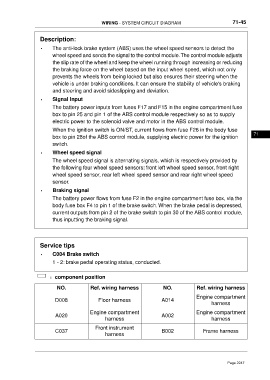
                   Description:

                   •     The anti-lock brake system (ABS) uses the wheel speed sensors to detect the
                         wheel speed and sends the signal to the control module.The control module adjusts
                         the slip rate of the wheel and keep the wheel running through increasing or reducing
                         the braking force on the wheel based on the input wheel speed, which not only
                         prevents the wheels from being locked but also ensures their steering when the
                         vehicle is under braking conditions. It can ensure the stability of vehicle's braking
                         and steering and avoid sideslipping and deviation.

                   •     Signal Input
                         The battery power inputs from fuses F17 and F15 in the engine compartment fuse
                         box to pin 25 and pin 1 of the ABS control module respectively so as to supply
                         electric power to the solenoid valve and motor in the ABS control module.
                         When the ignition switch is ON/ST, current flows from fuse F26 in the body fuse
                                                                                                                     71
                         box to pin 28of the ABS control module, supplying electric power for the ignition
                         switch.

                   •     Wheel speed signal
                         The wheel speed signal is alternating signals, which is respectively provided by
                         the following four wheel speed sensors: front left wheel speed sensor, front right
                         wheel speed sensor, rear left wheel speed sensor and rear right wheel speed
                         sensor.
                   •     Braking signal

                         The battery power flows from fuse F2 in the engine compartment fuse box, via the
                         body fuse box F4 to pin 1 of the brake switch. When the brake pedal is depressed,
                         current outputs from pin 2 of the brake switch to pin 30 of the ABS control module,
                         thus inputting the braking signal.


                   Service tips
                   •     C004 Brake switch

                         1 - 2: brake pedal operating status, conducted.


                        :component position

                           NO.            Ref. wiring harness              NO.            Ref. wiring harness
                                                                                          Engine compartment
                          D008                Floor harness               A014
                                                                                                 harness

                                          Engine compartment                              Engine compartment
                          A020                                            A002
                                                 harness                                         harness
                                            Front instrument
                          C037                                            B002               Frame harness
                                                 harness


                                                                                                        Page 2247

