Page 2299 - Foton Workshop Manual - Tunland (AT)
P. 2299
WIRING - SYSTEM CIRCUIT DIAGRAM                             71-97


                   Description:

                   •     When the car collides with an obstacle, an fully inflated air cushion is deployed
                         quickly, to make the occupants inside the car throw on the air cushion due to inertia,
                         thus alleviating the impact applied to the occupants and absorbing the collision
                         energy, to reduce the risk of injury.
                         When the ignition switch is in position ON/ST, current flows from fuse F24 of body
                         fuse box to pin 5 of the airbag control module, providing power to the airbag control
                         module.

                         When a collision occurs, current outputs from pin 10 of airbag control module to
                         pin 1 of the clock spring, via the clock spring to the pin of driver's airbag assembly,
                         then from the other end of driver's airbag to pin 2 of the clock spring and back to
                         pin 11 of the airbag control module via the clock spring, which forms a loop to ignite
                         the airbag.
                                                                                                                     71
                         When a collision occurs, the current outputs from pin 18 of airbag control module
                         to pin 1 of the passenger's airbag, and then from pin 2 of the passenger's airbag
                         to pin 19 of the airbag control module, which forms a loop to ignite the airbag.

                   •     Seat belt buckle switch
                         The current outputs from pin 30 of the airbag control module to pin 1 of the driver's
                         seat belt buckle switch,and it is grounded via pin 2 of the seat belt buckle switch,
                         to check if the seat belt is fastened. The current outputs from pin 37 of the airbag
                         control module to pin 1 of the passenger's seat belt buckle switch, and grounded
                         via pin 2 of seat belt buckle switch, to check if the seat belt is fastened.


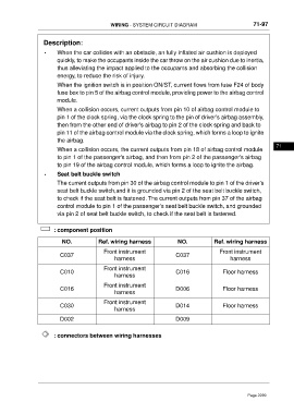
                        : component position

                           NO.            Ref. wiring harness              NO.            Ref. wiring harness

                                            Front instrument                                 Front instrument
                          C037                                            C037
                                                 harness                                         harness
                                            Front instrument
                          C010                                            C016                Floor harness
                                                 harness
                                            Front instrument
                          C016                                            D006                Floor harness
                                                 harness

                                            Front instrument
                          C030                                            D014                Floor harness
                                                 harness
                          D002                                            D009


                        : connectors between wiring harnesses


                                                                                                        Page 2299

