
Page 249 - Foton Workshop Manual - Tunland (AT)
P. 249
DIAGNOSTICS - ENGINE CONTROL SYSTEM 04-103
INTERMITTENT FAILURE
If an intermittent failure exists, diagnosis may be conducted as per the following steps:
WARNING
In many cases, intermittent failure may be eliminated by itself (the functions of a part
or circuit return to normal when no intervention is implemented).The phenomenon 04
complained by the customer might not reoccur when DTC is tested. In addition, the
most common causes of intermittent failures usually lie in the poor electric connectors.
Therefore, the state in which the failure occurred is not very clear. So, the circuit check,
which is part of the standard diagnosis steps, may fail to find out the specific failure
zones.
In such a case, we have to inquire the customer for the condition when the failure
happened, inquire the vehicle owner for the driving details, weather condition,
occurrence frequency and failure phenomena, carry out analysis, simulate the identical
or similar condition and environment in which the failure happened, and then verify
whether or not the failure phenomena were caused by vibration, temperature or other
factors.
No matter how the serviceman is experienced and skillful, some important factors will
certainly be ignored in process of repair if failure is analyzed without verification, and
incorrect guesses may urge the personnel to take a wrong path, or even the repair
cannot be carried out.
The following checks may be conducted to find out such failures.
1 . Vibration method.
When vibration is considered as the major cause of the failure, the connectors and
subassemblies may be checked so as to verify whether or not the failure phenomena
occur. Failure simulation may be performed as per the following procedures:
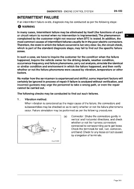
(a) Connector: Shake the connectors gently in
vertical and horizontal directions, and check
whether or not the harness connectors
connected to corresponding parts get loose.
Check the terminals for soil, rust, corrosion,
and bend. Check for any loose contact caused
by elongation of terminals.
Page 249