
Page 294 - Foton Workshop Manual - Tunland (AT)
P. 294
04-148 DIAGNOSTICS - ENGINE CONTROL SYSTEM
DTC inspection
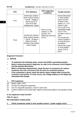
DTC DTC definition Trouble location
conditions
Accelerator pedal or • Accelerator pedal
lever position sensor or lever position
1 circuit - Voltage is signal circuit is
P131
04 above normal or shorted to the
shorted to high battery or (+) 5V
voltage power supply. power supply.
• The circuit of the
• When the key accelerator pedal
switch is in ON circuit in the
position, the harness or joint is
Accelerator pedal or diagnosis continues open
lever position sensor to run. • The accelerator
1 circuit - Voltage is power supplies is
P132
below normal or shorted circuit to
shorted to low voltage the battery
power supply. • Accelerator pedal
or lever position
sensor is fault
• ECM
Diagnosis Procedure
NOTICE
• To implement the following steps, ensure that ECM is grounded properly.
• Before conducting electric diagnosis, do refer to the reference circuit diagram
and the element information.
• Before conducting measurement, check the pins of connectors for rupture,
looseness and rust, and ensure that the pins are contacted properly.
• If the connection is good, check the sensor signal voltage when moving the
connector and harness. If a fault occurs, the voltage display on the diagnostic
instrument will change.
1 . DTC inspection
(a) Ignition switch: OFF.
(b) Connect the diagnostic apparatus.
(c) Use the diagnostic apparatus, read the fault code.
(d) Confirm whether there is fault code related to accelerator pedal or lever position sensor
1?
Is the inspection result normal?
YES>To step 2.
NO>Intermittent trouble exists.
2 . Check accelerator pedal or lever position sensor 1 power supply circuit
Page 294