
Page 290 - Foton Workshop Manual - Tunland (AT)
P. 290
04-144 DIAGNOSTICS - ENGINE CONTROL SYSTEM
DTC inspection
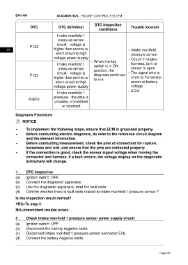
DTC DTC definition Trouble location
conditions
Intake manifold 1
pressure sensor
circuit - voltage is
P122
04 higher than normal or • Intake manifold
short circuit to high pressure sensor
voltage power supply • Circuit in engine
• When the key
Intake manifold 1 harness, joint or
switch is in ON
pressure sensor sensor is open
position, the
circuit - voltage is • The signal wire is
P123 diagnosis continues
higher than normal or short to the sensor
to run
short circuit to high power or battery
voltage power supply voltage
• ECM
Intake manifold 1
pressure - the data is
P2973
unstable, intermittent
or incorrect
Diagnosis Procedure
NOTICE
• To implement the following steps, ensure that ECM is grounded properly.
• Before conducting electric diagnosis, do refer to the reference circuit diagram
and the element information.
• Before conducting measurement, check the pins of connectors for rupture,
looseness and rust, and ensure that the pins are contacted properly.
• If the connection is good, check the sensor signal voltage when moving the
connector and harness. If a fault occurs, the voltage display on the diagnostic
instrument will change.
1 . DTC inspection
(a) Ignition switch: OFF.
(b) Connect the diagnostic apparatus.
(c) Use the diagnostic apparatus, read the fault code.
(d) Confirm whether there is fault code related to intake manifold 1 pressure sensor ?
Is the inspection result normal?
YES>To step 2.
NO>Intermittent trouble exists.
2 . Check intake manifold 1 pressure sensor power supply circuit
(a) Ignition switch: OFF.
(b) Disconnect the battery negative cable.
(c) Disconnect intake manifold 1 pressure sensor connector E08.
(d) Connect the battery negative cable.
Page 290