
Page 368 - Foton Workshop Manual - Tunland (AT)
P. 368
04-222 DIAGNOSTICS - ENGINE CONTROL SYSTEM
P584,P585-STARTING MOTOR RELAY DRIVE CIRCUIT FAULT
P584-STARTING MOTOR RELAY DRIVE CIRCUIT -VOLTAGE IS
ABOVE NORMAL OR SHORTED TO HIGH VOLTAGE POWER
SUPPLY
04 P585-STARTING MOTOR RELAY DRIVE CIRCUIT -VOLTAGE IS
BELOW NORMAL OR SHORTED TO HIGH VOLTAGE POWER
SUPPLY
Description
1 . The engine control module (ECM) controls the starting motor locking relay by
starting motor locking relay signal circuit. When the engine runs, the relay
prevents the starting motor from engaging.The relay loop is dependent on the
OEM wire. On some vehicles, it may connect back to the ECM, or on the other
vehicle, it connects to the chassis or cylinder. For loop details, refer to the
electrical wiring diagram of OEM.The starter motor locking relay circuit uses a
pulse width modulation (PWM) signal.The PWM signal is a pulse voltage signal
between the 0-VDC and the system voltage.The frequency of this pulse voltage
signal depends on the require of application type.
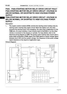
Circuit Diagram
Battery Ignition switch
A301 C201 L-R ON or START
17
F3 F17 F33
30A 5A 5A
2 5 4 Indoor
3 1 Engine fusebox
compartment C037
Start relay R3 fusebox A020 Start cut-off
relay R04
5 2 1 3
R-G R-Br
B
R 9 A303
C102 R B Front blower relay/
R-G rear defrost relay/
C714 L-W rearblower relay
2 P201 B1
A101
1 K101 R-G 2 A306
10 C105
P/N
R Shift control L-W
P002
1
4 3 2 1 7 5 6
NO. AM1 ST1 ACC IG1 ST2 AM2 IG2
Gear
Starter LOCK
M K005
ACC Ignition switch
C006
ON
Self-ground ST ftwxd041254
Page 368