
Page 371 - Foton Workshop Manual - Tunland (AT)
P. 371
DIAGNOSTICS - ENGINE CONTROL SYSTEM 04-225
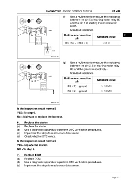
(f) Use a multimeter to measure the resistance
between the pin 5 of starting motor relay R3
and the pin 1 of starting motor connector
K005.
F11 F12 F13 F16 F15 F14 F30 F17
F29 2 2 2 F18 Standard resistance
3 5 3 5 3 5 4 A020
4 R3 R13 4 R7 1 F19
1 1 F20
2
85 85
30 30 3 5 4 Multimeter connection 04
R4 R16 R6 1
86 87 86 87 Standard value
pin
R3(5)- K005(1) <2 Ω
K005
1
ftwxd041185
(g) Use a multimeter to measure the resistance
between the pin 2, 5 of starting motor relay
R3 and the ground respectively.。
Standard resistance
F11 F12 F13 F16 F15 F14 F30 F17
F29 2 2 2 F18 A020
3 5 3 5 3 5 4
4 4 F19
R3 R13 R7 1
1 1 F20 Multimeter connection
2 Standard value
85 85
30 30 3 5 4
R4 R16 R6 1 pin
87 87
86 86
R3(2)- ground > 10 MΩ
R3(5)- ground > 10 MΩ
ftwxd041183
Is the inspection result normal?
YES>To step 6.
No > Maintain or replace the harness.
6 . Replace the starter
(a) Replace the starter.
(b) Use a diagnostic apparatus to perform DTC verification procedures.
(c) Implement the steps to read sensor data stream.
(d) Check whether DTC exists.
Is the inspection result normal?
YES>Replace the starter.
NO >To step 7.
7 . Replace ECM
(a) Replace ECM.
(b) Use a diagnostic apparatus to perform DTC verification procedures.
(c) Implement the steps to read sensor data stream.
Page 371