
Page 461 - Foton Workshop Manual - Tunland (AT)
P. 461
DIAGNOSTICS - ENGINE CONTROL SYSTEM 04-315
NOTICE
• To implement the following steps, ensure that ECM is grounded properly.
• Before conducting electric diagnosis, do refer to the reference circuit diagram
and the element information.
• Before conducting measurement, check the pins of connectors for rupture,
04
looseness and rust, and ensure that the pins are contacted properly.
• If the connection is good, check the sensor signal voltage when moving the
connector and harness. If a fault occurs, the voltage display on the diagnostic
instrument will change.
1 . DTC inspection
(a) Ignition switch: OFF.
(b) Connect the diagnostic apparatus.
(c) Use the diagnostic apparatus, read the fault code.
(d) Confirm whether there is fault code related to postprocessing 1 diesel oxidation
converter inlet temperature sensor circuit?
Is the inspection result normal?
YES>To step 2.
NO>Intermittent trouble exists.
2 . Check DPF temperature sensor circuit
(a) Ignition switch: OFF.
(b) Disconnect the battery negative cable.
(c) Disconnect DPF temperature sensor connector Q01.
(d) Connect the battery negative cable.
(e) Ignition switch: ON.
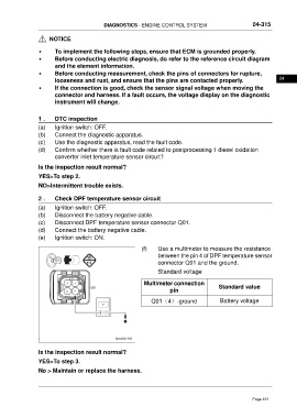
(f) Use a multimeter to measure the resistance
between the pin 4 of DPF temperature sensor
connector Q01 and the ground.
Standard voltage
Multimeter connection
Standard value
pin
Q01(4)-ground Battery voltage
Is the inspection result normal?
YES>To step 3.
No > Maintain or replace the harness.
Page 461