
Page 272 - Workshop Manual - Tunland (2017)
P. 272
04-134 DIAGNOSTICS - REVERSE RADAR SYSTEM
Diagnostic steps
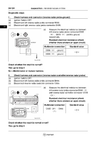
1 . Check harness and connector (reverse radar probe-ground)
(a) Ignition Switch: OFF.
(b) Disconnect left reverse radar probe connector B006.
(c) Disconnect right reverse radar probe connector B009.
04
(d) Measure the electrical resistance between
left reverse radar probe connector B006
(4)、B009(4) and the ground
respectively.
Standard electrical resistance (check
whether there existent an open circuit)
Multimeter connection Standard value
B006(4) - ground
<2Ω
B009(4) - ground
Check whether the result is normal?
Yes> go to step 2
No > Maintenance or replace harness.
3 . Check harness and connector (reverse radar controller-reverse radar probe)
(a) Ignition Switch: OFF.
(b) Disconnect left reverse radar probe connector B006.
(c) Disconnect reverse radar controller connector C035.
(d) Measure the electrical resistance between
left reverse radar probe connector B006(1)
and reverse radar controller connector C035
(31).
Standard electrical resistance (check
whether there existent an open circuit)
Multimeter connection Standard value
C035(31) - B006 <2Ω
(1)
Check whether the result is normal or not?
Yes> go to step 3