
Page 100 - Eden Meadow 35 houses application as of 12 October
P. 100
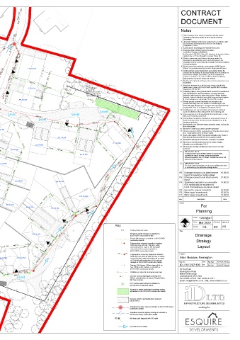
FW CONTRACT
150Ø 1:120
FW DOCUMENT
Notes
IL 30.103 drainage construction details all other relevant contract
gar 32.700 FW 1 This drawing is to be read in conjunction with the private
documents.
2 All private drainage works to be carried out in accordance with
the provisions laid down in BS EN 752 & The Building
IL 32.00 re IL 30.20 IL 30.20 Regulations, Part H.
IL 33.50 IL 31.85 100Ø IL 30.150 3 4 Levels shown in buildings are Finished Floor Level.
100Ø 1:80 100Ø a) Vitrified Clayware to BSEN295.
Drainage under adopted roads to be either:-
b) Concrete to BS 5911, Class M. Laterals to be formed of either
IL 32.18
150Ø 1:36
150Ø 1:15 FFL 33.000 1 IL 31.98 35 IL 32.00 5 Before commencing any Sewer or drainage works, the
vitrified clay or "Extra Strength", concrete "Class M",
re IL 34.30 IL 33.94 IL 32.80 IL 31.91 100Ø 1:40 Developer's Groundworker must satisfy themselves, the
developer and the Local Authority of actual levels and conditions
of existing sewers.
IL 32.85 IL 32.80 150Ø 1:120 gar 33.000 34 100Ø 1:80 6 Buried concrete to satisfy the requirements of BRE Special
150Ø 1:47
IL 34.10
100Ø 1:20 2 FFL 33.150 Digest 1 as predetermined by the site's Geotechnical Report
8 100Ø 1:31 IL 32.20 7 All abandoned, buried obstructions encountered during the
FFL 35.100 IL 32.42 SA-1 100Ø 1:80 100Ø 1:80 RG 150Ø 1:28 re construction of Highway & Drainage Works are to be broken out
FFL 35.550 Min CL 33.10 IL 31.86 IL 32.40 to bed level of drains and sewers, and to the formation of
IL 34.30 150Ø 1:24 IL 33.15 IL(in) 31.55 carparks and drives etc., and to sufficient depth to allow for
IL 33.20 150Ø 1:120 100Ø 1:27 Base of crates 30.55 IL 31.55 IL 31.86 8 Depth and Location of existing services to be traced prior to any
re IL 34.30 FFL 34.350 IL 33.15 Top of crates 31.75 IL 31.78 100Ø 1:40 IL 31.81 100Ø laying service company's mains and services.
Total volume = 13.7m3
IL 32.35 st IL 31.55 IL 31.62 150Ø 1:120 IL 32.31 excavation.
150Ø 1:12
5&6 150Ø IL 31.69 SA-2 9 All private drainage to be laid to levels shown using flexibly
IL 33.30
FFL 35.550 3.00m 100Ø 1:19 IL 31.69 jointed pipes, either uPVC to BS 4660 and BS 5481 or vitrified
CP IL 32.21 st CP 33.150 IL 32.50 st Min CL 32.90 clayware to BS EN 295.
IL 33.50 IL 32.28 Top of crates 31.90 10 Generally pipes to have granular Bed & Surround in accordance
FFL 35.400 225Ø 4.00m IL (in) 31.70
re IL 34.55 IL 32.16 IL 32.050
with manufacturers recommendations, ensuring adequate
Infiltration IL 32.10 IL 32.70 150Ø 1:120 Base of crates 30.70 protection with respect to depth and location. Where bedding
Total volume = 65m3
10 Basin RG IL 32.347 33 material is placed at depths susceptible to ground water ingress,
IL 35.00 100Ø 1:20 9 Infiltration 100Ø 1:40
IL 34.55
Basin IL 32.05 IL 32.45 FFL 33.525 IL 31.72 IL 31.70 it is to be wrapped in a geotextile (Terram 700 or better).
7 cp 11 Private precast concrete manholes and catchpits to be
re IL 34.95 IL 32.160 st
11 150Ø 1:62 FFL 34.950 150Ø 1:32 150Ø 1:120 150Ø 1:55 re 19.00m constructed using conc. box sections or circular rings to BS
4 IL 32.15 IL 32.75 5911-200, with 150mm conc. surround, size and construction to
comply with Table 12 of Approved Document, Part H.
IL 32.275 IL 32.20 re 12 Rodding eyes, etc are to be laid to manufacturers minimum
100Ø 1:36
225Ø
12 3 150Ø 1:22 IL 32.20 Level IL 31.70 cover and depth to allow adequate fall from adjoining unit.
IL 32.200
FFL 36.000 13 IL 33.70 RG IL 32.275 cp IL 33.41 Level 100Ø 1:80 Level CP IL 32.31 3.00m 13 Access panels are to be provided to all rainwater pipes, a max.
600 above finished ground level.
IL 33.70
All manholes / inspection chambers in hard surfaced areas, to
22 Level IL 32.38 14 have recessed covers. These are to be orientated such as to
150Ø 1:53
150Ø 1:26 100Ø 1:80
14 re re IL 33.30 32 minimise cut blocks.
15 IL 32.66 IL 32.86
FFL 36.000 IL 33.100 IL 33.60 150Ø 1:80 15 All pipework to be 100mmØ unless otherwise stated, 150mm dia
FFL 36.000 16 IL 33.15 150Ø 1:120 100Ø 1:10 100Ø 1:80 IL 33.16 IL 33.11 from road gullies.
re IL 35.25 IL 34.10 FFL 34.350 IL 33.16 150Ø 1:120 IL 33.04 IL 32.50 150Ø 1:40 31 16 All levels in metres (m) unless specified otherwise.
IL 33.100 st
17
All drain runs from SVP's, stub stacks or FW gullies to be laid at
FFL 35.700 150Ø 1:25 3.00m min. 1:40 gradient unless otherwise stated.
cp 150Ø 1:120 IL 32.95 100Ø 1:80 18 Svp's, stub stacks & RWP's are shown indicative only. Refer to
Architectural dimensioned GA's for accurate locations
IL 34.10
FFL 35.250 SA-3 IL 33.29 IL 33.37 FFL 34.200 100Ø 1:80 100Ø 19 House/Flat drainage to be laid prior to erection of scaffold.
Min CL 34.35
225Ø IL 33.02 FFL 33.900 20 All cover and invert levels shown are in metres. All pipe
IL 33.700 Top of crates 33.35 IL 33.15 CP IL 33.29 IL 33.49 gar 34.200 IL 33.04 IL 32.79 21 diameters are in millimetres U.N.O.
IL (in) 33.15
150Ø 1:34
All chambers located in trafficked areas to have concrete
Base of crates 32.15
RG
Total volume = 82m3
150Ø 1:50
gar 34.350 re IL 33.45 100Ø 1:80 100Ø 1:80 surround.
IL 33.21
100Ø 1:20 150Ø IL 33.31 gar 34.200 22 IMPORTANT NOTE:
150Ø
At depths where groundwater ingress is encountered,
consider the use of a sump / pump arrangement.
24.00m 225Ø 1:20 23 IL 33.44 st IL 33.15 re Where excavations are >1m deep, consider the use of full
perimeter trench support.
IL 33.85
IL 33.85
st IL 33.75 IL 32.65 100Ø 1:20
150Ø 1:13
IL 34.80 FFL 34.950 150Ø 1:25 23 IMPORTANT NOTE:
The new sewer connections are be successfully made prior
IL 33.69 IL 34.07 IL 33.82 to commencing any upstream drainage works.
150Ø 1:34
gar 36.450 100Ø IL 33.15 IL 34.20 P6 Drainage revised to suit latest scheme 10.09.20
re IL 36.60 150Ø 1:20 225Ø 1:20 100Ø 1:39 re layout. Exceedance routing added
100Ø 1:20
IL 35.70 IL 34.75 24 IL 33.94 IL 33.54 P5 Drainage revised to suit latest scheme 01.09.20
IL 35.72 layout.
FFL 37.350 gar 34.950 gar 35.250
P4 Soakaways resized to accommodate 14.05.20
cp IL 34.25
IL 34.25
17 IL 34.12 FFL 35.550 FEH rainfall data as requested by
IL 35.67
LLFA. Permeable paving details added.
100Ø 1:12 100Ø 1:60 150Ø 1:60
FFL 36.450 RG P3 Revised to Esquire comments 23.03.20
18 100Ø 1:28 P2 Minor layout amendments 20.03.20
IL 35.100 225Ø 1:20 25 re 100Ø 1:20 FFL 35.250 IL 33.74 Rev Description Date
FFL 37.350 IL 34.80 IL 34.62 P1 Minor layout amendments 13.03.20
150Ø 1:120
IL 35.15 100Ø 1:20 IL 34.75 IL 34.95 100Ø 1:23 Status:
21 gar 36.450 gar 35.550
IL 34.82 gar 35.700 FFL 35.700 150Ø 1:60 IL 34.18
re IL 36.30 For
IL 36.55
100Ø 1:17 IL 34.90 IL 34.95 FFL 36.000 100Ø 1:23 IL 34.00 IL 33.95 100Ø 1:80 30 Planning
150Ø 1:80
100Ø 1:80
150Ø 1:120 IL 35.40 IL 33.95
IL 35.94
20 IL 36.26 150Ø IL 35.50 IL 35.50 100Ø 1:60 150Ø 1:120 150Ø 1:31 IL 35.80 100Ø 1:40 IL 35.25 re IL 35.10 IL 34.30 Scale : 1:250@A1
IL 35.55
19
IL 36.00
IL 35.21 100Ø IL 35.20 re 150Ø 1:25 29 Key Date : Mar 2020 Checked: Approved:
DC
PT
Drawn :
IDL
IL 35.90
26 100Ø 1:27 Existing foul water sewer
Title :
gar 36.000 FFL 36.150 Private foul water drainage as detailed on
IL 36.00 IL 34.56 IL 34.51 100Ø 1:25 IDL/1012/07/ construction details. Drainage
FFL 36.750 Private SW drainage as detailed on IDL/1012/07/
re construction details.
IL 34.51 Strategy
IL 35.42 28 Polypropylene universal inspection chambers
100Ø 1:20 150Ø 1:25 1200 deep max, 450 dia, 100 inlet / outlet
gar 36.750 IL 36.00 Layout
re 100Ø connections (6 no. max) or 150 inlet/outlet
Level DW IL 34.86 IL 34.81 connections (4 no max) as detailed on
IDL/1012/07/ construction details.
Oven nme nme
IL 34.81 Polypropylene 'non-entry' inspection chambers Project :
gar 36.750 FFL 36.750 3000 deep max, 450 dia (with 300 dia. or square Eden Meadow, Newington
cover) 100 inlet / outlet connections (6 no. max),
150Ø 1:25 or 150 inlet/outlet connections (4 no max) as Drg. No: Rev: File Ref: 1012-07-100.dwg
IL 36.00
detailed on IDL/1012/07/ construction details.
80mm thick Brett Alpha Flow, concrete block paviors. IDL/1012/07/100 P6
Joints to be filled with bedding aggregate 100Ø 1:35 Hall Denotes 250 dia ppic, 600mm deep with 4 no. Plot Ref: 1012-07-100.pdf
max 100 dia inlets / outlets, as detailed on
50mm compacted thickness of bedding stone to BS Level IL 35.50 IDL/1012/07/ construction details. 33 The Point
EN13242:2002, Type 2/6.3 Gc 80/20 IL 35.65 IL 35.95 27 100Ø 1:20 re Rodding eye same dia. as downstream drain Rockingham Road
IL 35.25
Base: 80mm Recipe mix AC 20 dense binder 40/60 to IL 35.60 150Ø 1:32 Denotes 450 dia polypropylene silt trap with Market Harborough
Leicestershire LE16 7QU
EN13108-1 (to be core drilled on a 750x750mm grid using a 60mm thick Brett Alpha Flow, concrete block paviors. Level ST 300mm nominal sump, as messrs Polypipe Basic Tel: 01858 411570 Fax: 01858 411571
50mm drilled hole prior to laying bedding course and blocks. Joints to be filled with bedding aggregate Silt Trap or similar.
Email: info@infrades.co.uk URL: www.infrades.co.uk
Holes to be filled with bedding aggregate. 50mm compacted thickness of bedding stone to BS
CP PCC surface water catchpit as detailed on
350mm thickness of course aggregate subbase to BS EN EN13242:2002, Type 2/6.3 Gc 80/20 IDL/1012/07/ construction details
13242:2002 Type 4/20 (top 150mm) Type 4/40 (lower 200mm). 350 thickness of course aggregate subbase to BS EN 13242:2002
Aquacell or similar crate-based soakaway system
Single layer of Terram 1000 to base and sides of subase at formation level. Type 4/20 (top 150mm) Type 4/40 (lower 200mm). as detailed on IDL/1012/07/03 construction details
Single layer of Terram 1000 to base and sides of subase at formation level.
Denotes extent of permeable block paving to
private drives
INFRASTRUCTURE DESIGN LIMITED
Adoptable foul water sewer as detailed on IDL/1012/03 series working for
construction details.
Adoptable standard highway drainage as detailed on
IDL/1012/02 series construction details.
RG 900 deep gully (trapped) with 150 outlet.
Exceedance flow routing
Permeable Block Paved Access Roads Permeable Block Paved Parking Bays / Driveways